Lamplight device for simulating planet and control method thereof
A planetary and lighting technology, applied to lighting devices, fixed lighting devices, lighting device components, etc., can solve the problem that lighting cannot be controlled at a single point
- Summary
- Abstract
- Description
- Claims
- Application Information
AI Technical Summary
Problems solved by technology
Method used
Image
Examples
Embodiment 1
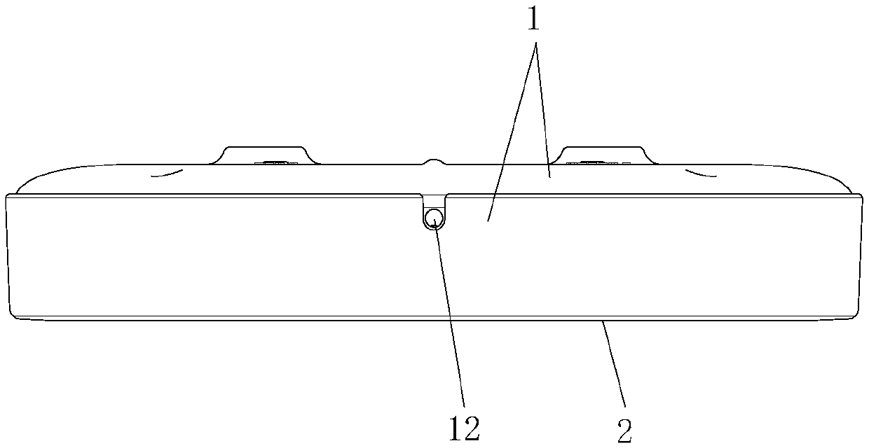
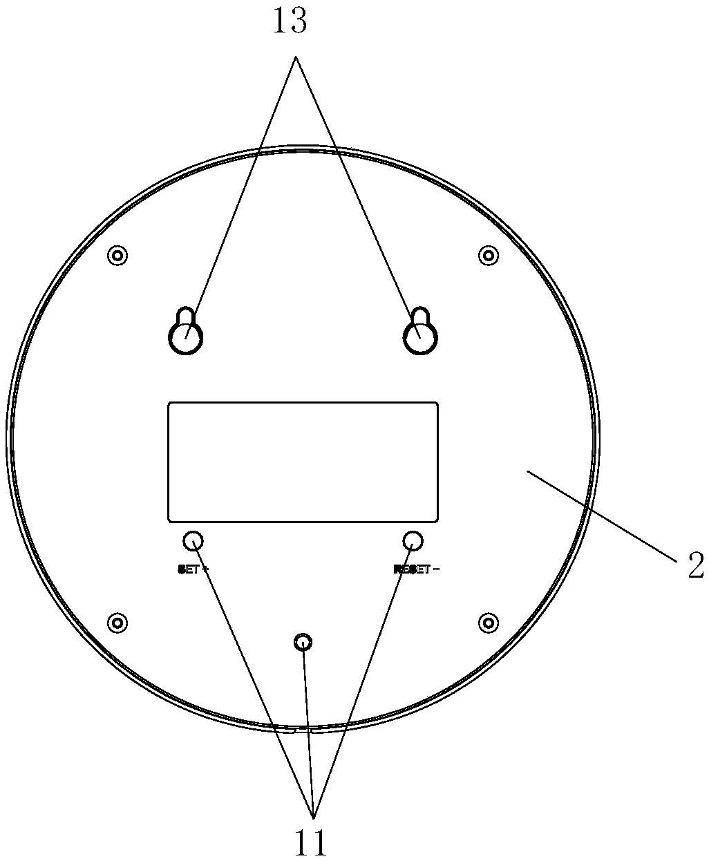
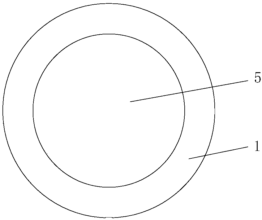
[0038] Such as Figure 1-6 As shown, this embodiment provides a lighting device for simulating a planet, which includes a housing, a luminous element, and a decorative plate 3 for simulating the surface of a planet. Wherein the decorative plate 3 is in the shape of a disc, and its outer surface is provided with a concave-convex texture simulating a planet. When the light is irradiated from the side of the ornamental plate 3, since the concave-convex texture will block part of the light, the edge portion of the ornamental plate 3 will be brighter than the middle portion, further improving the realism of the simulated planet. The following materials and methods can be used for the production of decorative plate 3:
[0039] It can be shaped by ceramic engraving over-molding, which replaces the ceramic material with a mixture of resin and cement. Metal and resin mixed materials can also be used, and the process of die-casting, pouring and CNC milling can be used to form, and the...
Embodiment 2
[0046] Such as Figure 7-10 As shown, most of the technical features in the second embodiment are the same as those in the first embodiment, except that:
[0047] The luminous part includes a circular circuit board 6, and the upper surface of the circuit board 6 is distributed with LED lamp groups 8 along the circumferential direction; the circuit board 6 is fixed on the mounting column 4, and the decorative plate 3 is fixed on The upper surface of the circuit board 6 and the LED lamp group 8 surround the surroundings of the decorative plate 3 . The decorative plate 3 is fixed on the upper surface of the circuit board 6 through the second light guide ring 14; the cross section of the second light guide ring 14 is L-shaped, and the end surface of one of the two ends of the second light guide ring 14 is provided with a ring through the groove 10 so that the end surface of this end covers the LED lamp group 8, and the other end is sandwiched between the upper casing 1 and the de...
Embodiment 3
[0050] This embodiment provides a control method for a lighting device, which is applied to the lighting device for simulating a planet in Embodiment 1 or Embodiment 2, including the following steps:
[0051] Step 1: Set the first LED light on and the first LED light off in the LED light group through the circuit board, and set the time interval T on the circuit board. The crystal oscillator chip on the circuit board is used for timing, and the processor chip is used to control the on and off of the LED lights.
[0052] Step 2: When the first set LED lights up, after time T, the two adjacent LED lights on both sides of the LED light that lights up for the first time light up and the brightness gradually increases; The two outer LED lights adjacent to the two LED lights that light up for the second time light up and the brightness gradually increases; thus the cycle continues until all the LED lights on the LED light group are all lit;
[0053] Step 3: When the first LED light...
PUM
 Abstract
Description
Claims
Application Information
 - R&D
- Intellectual Property
- Life Sciences
- Materials
- Tech Scout
- Unparalleled Data Quality
- Higher Quality Content
- 60% Fewer Hallucinations
Browse by: Latest US Patents, China's latest patents, Technical Efficacy Thesaurus, Application Domain, Technology Topic, Popular Technical Reports.
© 2025 PatSnap. All rights reserved.Legal|Privacy policy|Modern Slavery Act Transparency Statement|Sitemap|About US| Contact US: help@patsnap.com


