Cable temporary joint structure for test device

A technology of testing equipment and joint structure, which is applied in the direction of testing/measuring connectors, connections, fixed connections, etc. It can solve the problems of increased cumbersomeness, tediousness, unfavorable repeated testing, etc., and achieve the effect of high connection firmness and convenient use

Inactive Publication Date: 2019-04-16
湖州格雷电力电缆有限公司
View PDF4 Cites 0 Cited by
  • Summary
  • Abstract
  • Description
  • Claims
  • Application Information

AI Technical Summary

Problems solved by technology

[0002] The wiring device of cable testing equipment is a very important part. The existing wiring device is usually a copper column. In actual use, the end of the cable needs to be processed, wound into a loop or made into a crocodile clip connection. Copper pillars, this method is very cumbersome and is not conducive to repeated testing. At the same time, when it is necessary to test each connection point in the actual detection process, after connecting in this way, the alligator clips and pins used for testing are easy to loosen the cable. The connection between the end and the copper column further increases the complexity of use

Method used


Image

  • Cable temporary joint structure for test device
  • Cable temporary joint structure for test device

Examples


Embodiment Construction

[0017] The present invention will be described in further detail below in conjunction with the accompanying drawings.

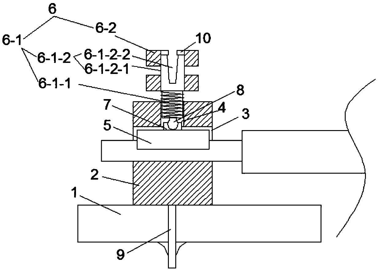
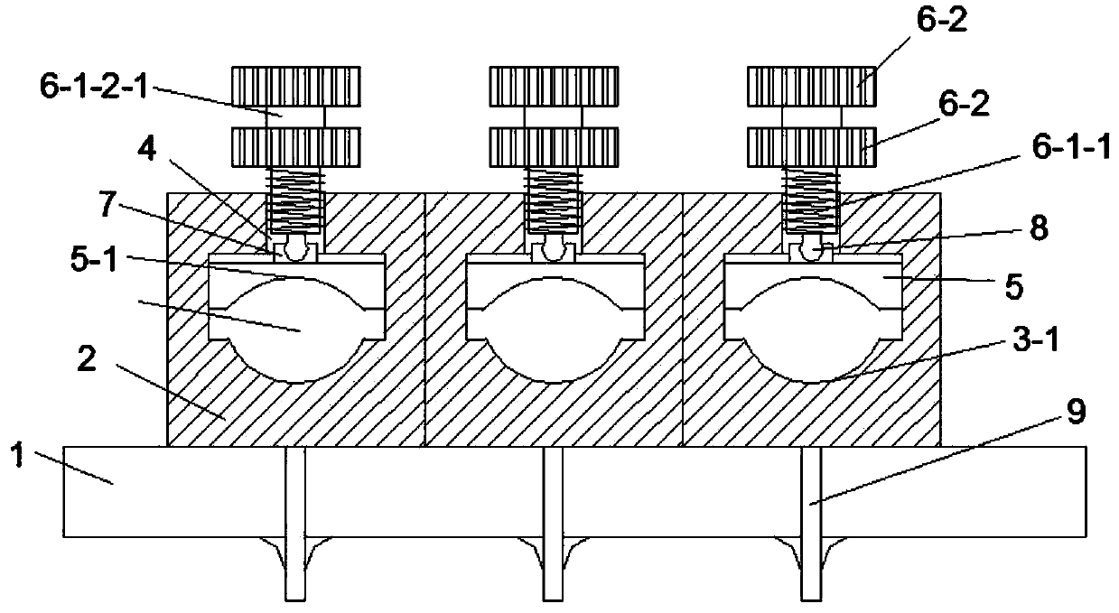
[0018] Such as figure 1 , figure 2 As shown, the embodiment of the present invention includes a connecting pile 2 arranged on the base 1, the connecting pile 2 is provided with a cable connection hole 6-1-2-23, the top of the connecting pile 2 has an adjustment through hole 4, and the cable The connection hole 6-1-2-23 is provided with a compression plate 5, and the adjustment through hole 4 is screwed with an adjustment conduction knob 6, and the lower end of the adjustment conduction knob 6 is rotationally connected with the top of the compression plate 5, and the adjustment guide The through knob 6 and the pressing plate 5 are all conductor materials. Both the conduction knob 6 and the pressing plate 5 are made of copper.

[0019] Such as figure 1 , figure 2 As shown, the top of the pressing plate 5 of the embodiment of the present invention is prov...


PUM


Abstract

A cable temporary joint structure for a test device comprises a connecting pile, wherein the connecting pile is provided with a cable connecting hole; the top of the connecting pile is provided with an adjusting through hole; the cable connecting hole is provided therein with a pressing plate; the adjusting through hole is in threaded connection with a regulating turn-on knob; the lower end of theadjusting turn-on knob is rotatably connected with the top of the pressing plate; and the adjusting turn-on knob and the pressing plate are both made of electrical conductors. The cable temporary joint structure solves the problems in the prior art by using the pressing plate in cooperation with the regulating turn-on knob having a connecting hole and a connecting post.

Description

technical field [0001] The invention relates to the technical field of cable wiring devices, in particular to a temporary cable joint structure for testing equipment. Background technique [0002] The wiring device of cable testing equipment is a very important part. The existing wiring device is usually a copper column. In actual use, the end of the cable needs to be processed, wound into a loop or made into a crocodile clip connection. Copper pillars, this method is very cumbersome and is not conducive to repeated testing. At the same time, when it is necessary to test each connection point in the actual detection process, after connecting in this way, the alligator clips and pins used for testing are easy to loosen the cable. The connection between the end and the copper pillar further increases the complexity of use. Contents of the invention [0003] The object of the present invention is to provide a temporary cable joint structure for testing equipment. The present...

Claims


Application Information

Patent Timeline
IPC IPC(8): H01R12/51H01R4/36
CPCH01R4/366H01R12/515H01R2201/20
Inventor 何立立周秋峰
Owner 湖州格雷电力电缆有限公司
Why Eureka
Try Eureka