
A cleaning device for teaching electrical appliances

A technology for cleaning devices and electrical appliances, which is applied to the cleaning methods, cleaning methods and utensils, chemical instruments and methods using gas flow, etc. , high cleaning efficiency, good cleaning effect

Active Publication Date: 2020-05-12
SHANDONG LABOR VOCATIONAL & TECHN COLLEGE
View PDF8 Cites 0 Cited by
  • Summary
  • Abstract
  • Description
  • Claims
  • Application Information

AI Technical Summary

Problems solved by technology

[0002] In electromechanical teaching, a large number of experiments are needed to help students better understand electrical principles, mechanical movement processes and electromechanical linkage processes. Therefore, a large number of electronic instruments are required in the laboratory, such as indicating instruments, frequency meters, phase meters, and synchronization indicators. Instruments, resistance measuring instruments, and electronic instruments commonly used in electrical measurement, etc. Many instruments need to be handed in during use, but electronic instruments will have a lot of dust after long-term use, especially some electronic instruments that have been used for a long time Placed in corners and warehouses, too much dust will cause failure of electrical instruments and affect teaching;
[0003] When cleaning electrical instruments, they need to be wiped and cleaned one by one, and they should not be wiped with water, which is time-consuming and laborious. At the same time, when manually wiping precision parts such as instrument line connectors, it is easy to cause damage to the electronic instruments and make them unusable.

Method used


Image

  • A cleaning device for teaching electrical appliances
  • A cleaning device for teaching electrical appliances
  • A cleaning device for teaching electrical appliances

Examples


Embodiment Construction

[0037] In order to enable those skilled in the art to better understand the technical solutions in the present invention, the technical solutions in the embodiments of the present invention will be clearly and completely described below in conjunction with the drawings in the embodiments of the present invention. Obviously, the described The embodiments are only some of the embodiments of the present invention, not all of them. Based on the embodiments of the present invention, all other embodiments obtained by persons of ordinary skill in the art without making creative efforts shall fall within the protection scope of the present invention.

[0038] For the convenience of description, the coordinate system is defined as figure 1 shown.

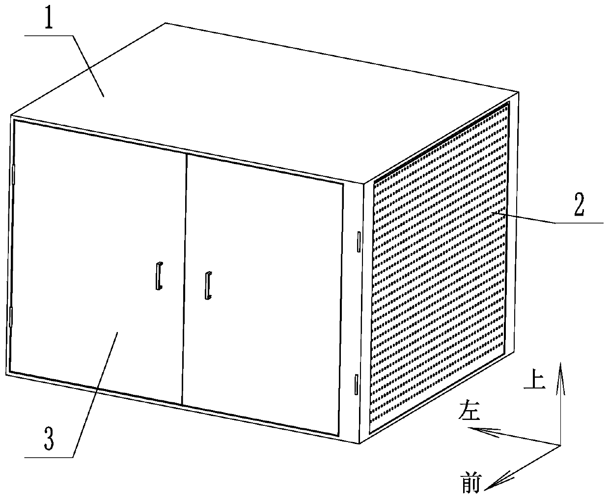
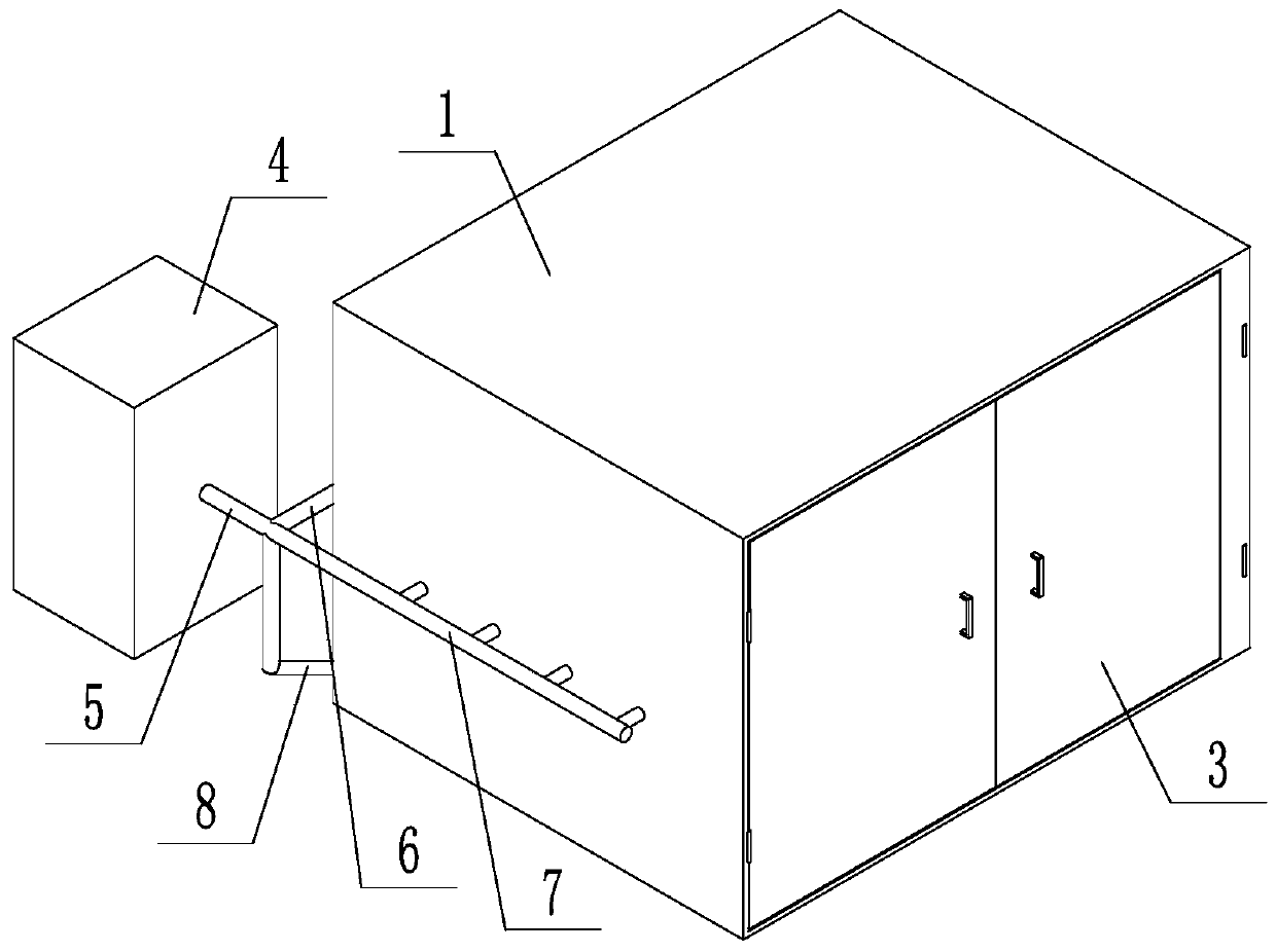
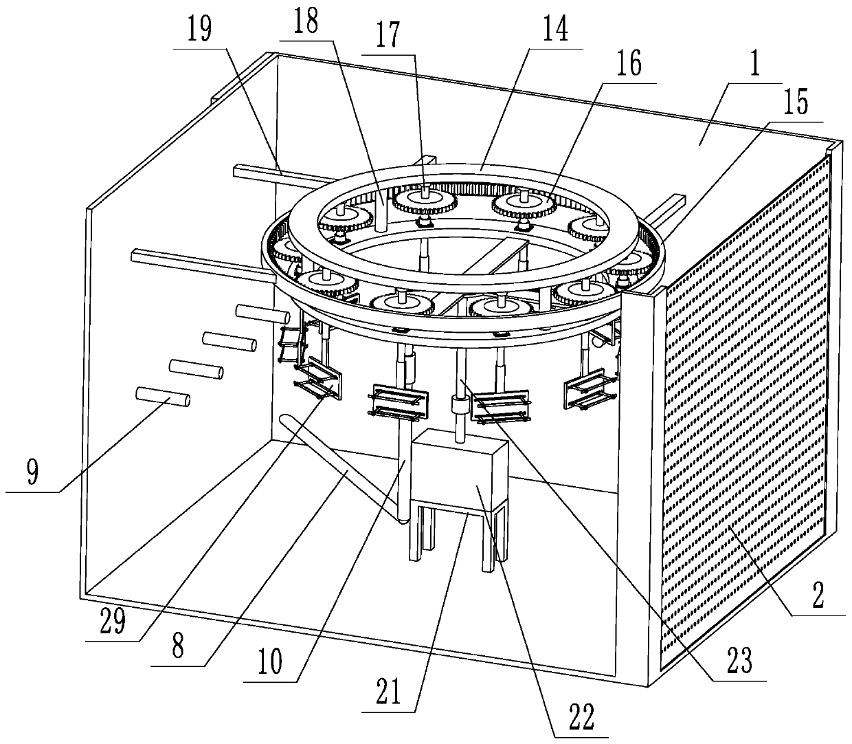
[0039] like Figure 1 to Figure 11As shown, a cleaning device for teaching electrical appliances includes a housing 1, an air blowing system and a rotating device. The air blowing system includes a gas source 4, a main gas pipeline 5 and a...


PUM


Abstract

The invention discloses an electrical appliance instrument cleaning device for teaching. The electrical appliance instrument cleaning device for teaching comprises a housing, a gas blowing system anda rotating device, wherein the gas blowing system comprises a gas source, a primary gas pipeline and a branch gas pipeline; the branch gas pipeline extends into the housing; the rotating device comprises a rotating frame, a first rack and a drive device; the first rack is connected to the inner wall of the housing; the output end of the drive device is connected to the rotating frame; the rotatingframe comprises upper and lower ring-shaped plates; a first gear is arranged between the two ring-shaped plates; the first gear is engaged with the first rack; the first rotary shaft of the first gear is rotatably connected to the two ring-shaped plates; and the lower end of the first rotary shaft is equipped with a connecting mechanism. Gas in the gas source sequentially passes through the primary gas pipeline, and the branch gas pipeline to enter the housing; and electrical appliance instruments revolute along with the rotating frame, and also automatically rotate along with the first rotary shaft, so that the electrical appliance instruments can be comprehensively and quickly cleaned, and therefore, cleaning efficiency is high and the cleaning effect is good.

Description

technical field [0001] The invention relates to the technical field of electrical instrument cleaning, in particular to a teaching electrical instrument cleaning device. Background technique [0002] In electromechanical teaching, a large number of experiments are needed to help students better understand electrical principles, mechanical movement processes and electromechanical linkage processes. Therefore, a large number of electronic instruments are required in the laboratory, such as indicating instruments, frequency meters, phase meters, and synchronization indicators. Instruments, resistance measuring instruments, and electronic instruments commonly used in electrical measurement, etc. Many instruments need to be handed in during use, but electronic instruments will have a lot of dust after long-term use, especially some electronic instruments that have been used for a long time Placed in corners and warehouses, too much dust will cause failure of electrical instrument...

Claims


Application Information

Patent Timeline
Patent Type & Authority Patents(China)
IPC IPC(8): B08B5/02
CPCB08B5/02
Inventor 董明华郑德荣周洪健周玮俐
Owner SHANDONG LABOR VOCATIONAL & TECHN COLLEGE
Learn More