Industrial conveying belt self-tensioning device

A conveyor belt and self-tensioning technology, applied in the field of mechanical devices, can solve problems such as complicated installation and loose belts

Pending Publication Date: 2019-04-19
南通欧炫工业制带有限公司
View PDF0 Cites 0 Cited by
  • Summary
  • Abstract
  • Description
  • Claims
  • Application Information

AI Technical Summary

Problems solved by technology

The installation of this structure is complicated. With the prolongation of the use time, when the translational travel of the tensioning wheel reaches the limit, the tensioning cannot be completed again, resulting in loosening of the belt and pre-conveying operations.

Method used


Image

  • Industrial conveying belt self-tensioning device
  • Industrial conveying belt self-tensioning device

Examples


Embodiment Construction

[0008] The present invention will be further described below in conjunction with the accompanying drawings and specific embodiments.

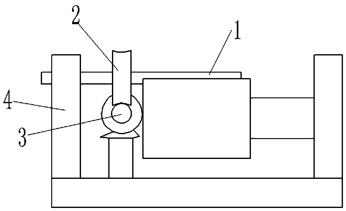
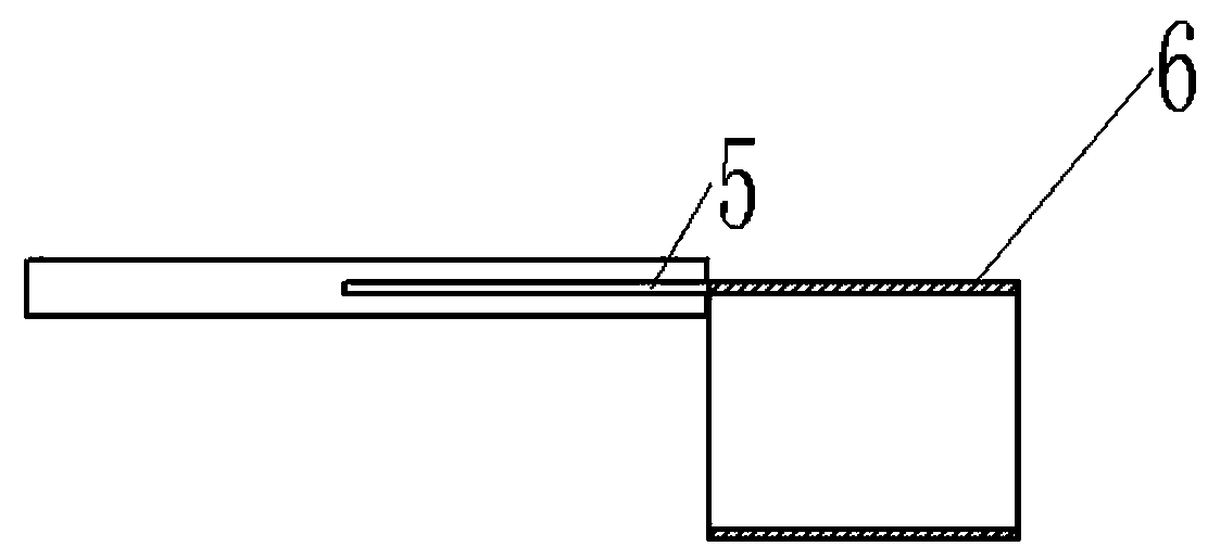
[0009] figure 1 , 2 Middle: clamp body 1, worm wheel 2, worm screw 3, frame 4, slot 5, conveyor belt 6.

[0010] An industrial conveyor belt self-tensioning device, the industrial conveyor belt self-tensioning device includes a clamping body 1, a worm wheel 2, a worm 3, and a frame 4, and the clamping body 1 is a columnar body, which is convenient for rotating and winding the transmission belt 6, to achieve tense purpose. One end of the snap-in body 1 is provided with a slot 5, and one end of the snap-in body 1 has a Y-shaped structure, and the snap-in body 1 is inserted into the conveyor belt 6 through the slot 5, and the snap-in body 1 is in addition One end is fixedly connected with the worm wheel 2, the worm 2 and the worm wheel 3 constitute a worm gear transmission mechanism, the worm 3 is fixedly connected with the motor reduction mech...


PUM


Abstract

The invention discloses an industrial conveying belt self-tensioning device. The industrial conveying belt self-tensioning device is characterized in that the industrial conveying belt self-tensioningdevice comprises a clamping and connecting body 1, a worm gear 2, a worm 3 and a rack 4, the clamping and connecting body 1 is a columnar body, an inserting groove 5 is formed in one end of the clamping and connecting body 1, one end of the clamping and connecting body 1 is of a Y-shaped structure, and the clamping and connecting body 1 and a conveying belt 6 are in inserted connection through the inserting groove 5. The industrial conveying belt self-tensioning device has the beneficial effects that the device can conduct tensioning in any period within the limited usage period of the belt,and limitation from the horizontal motion stroke of original tensioning wheels is avoided.

Description

technical field [0001] The invention relates to a mechanical device, in particular to an industrial conveyor belt self-tensioning device. Background technique [0002] The tensioning device of the belt needs to preset the tensioning wheel, and the tensioning wheel is translated through the translation mechanism to achieve the tension of the belt and realize the purpose of tensioning. This structure is complicated to install, and with the prolongation of the use time, when the translation stroke of the tensioning wheel reaches the limit, the tensioning cannot be completed again, resulting in loosening of the belt and pre-conveying operations. Contents of the invention [0003] The invention provides a self-tensioning device for industrial conveyor belts. The purpose of developing the device is set. The device omits the traditional tensioning wheel and adopts the simplified self-rotation winding method of the snap-in body 1 for tensioning. The device can be used on the belt ...

Claims


Application Information

Patent Timeline
Patent Type & Authority Applications(China)
IPC IPC(8): B65G23/44
CPCB65G23/44
Inventor 王茂年
Owner 南通欧炫工业制带有限公司
Why Eureka
Try Eureka