Belt tensioning device and belt conveyor applying same

A belt conveyor and tensioning device technology, applied in the direction of conveyors, transportation and packaging, etc., can solve the problems of narrowing the application field, inconvenient site layout, and application field restrictions, and achieve flexible setting, convenient production, and simple operation Effect

Pending Publication Date: 2022-05-17
BERIS ENG & RES CORP +1
View PDF6 Cites 0 Cited by
  • Summary
  • Abstract
  • Description
  • Claims
  • Application Information

AI Technical Summary

Problems solved by technology

The belt tensioning device of the spiral tension type is installed at the wheel frame of the tail redirecting wheel of the belt conveyor, and the tail redirecting wheel is displaced by adjusting the length of the screw to tighten the belt in the length direction of the belt. The tensioning force of the belt tensioning device is limited and can only be applied to smaller belts, and it takes up a large space at the rear of the rack, which brings some inconvenience to the site layout. In addition, the belt tensioning device is set at the rear turning wheel The device also results in the drive wheel being set only at the head, narrowing the field of application
The heavy hammer type belt tensioning device is installed on the lower belt surface of the belt. The tensioning roller is connected with the heavy hammer through a steel wire rope. By adjusting the weight of the heavy hammer, the displacement of the tensioning roller is adjusted to adjust the tightness of the belt. The belt tensioning device requires a certain space for installing the weight at the lower part of the belt, so the application field is also greatly restricted

Method used


Image

  • Belt tensioning device and belt conveyor applying same

Examples


Embodiment Construction

[0020] In order to better understand the purpose, structure and function of the present invention, the present invention will be further described in detail below in conjunction with the accompanying drawings.

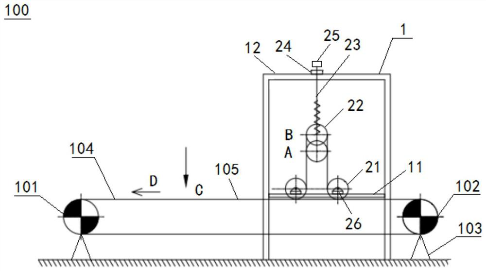
[0021] figure 1 The structure of the belt tensioning device according to the embodiment of the present invention is shown. The belt tensioning device includes: a fixed frame 1 and an adjusting device fixed in the fixed frame 1, the adjusting device includes a pair of fixed steering rollers 21 fixed in the fixed frame, and a tensioning roller 22 positioned above the pair of fixed steering rollers 21 , and the spiral tension rod assembly, one end of the spiral tension rod assembly is connected to the tension drum 22, and the other end is connected to the fixed frame 1, wherein the adjustment device is connected to the upper belt surface 105 of the belt 104 of the belt conveyor 100, After the upper belt surface 105 passes through the first fixed turning roller and the te...


PUM


Abstract

The invention belongs to the technical field of metallurgical belt feeding, and discloses a belt tensioning device and a belt conveyor applying the same. The belt tensioning device comprises a fixing frame and an adjusting device fixed in the fixing frame, the adjusting device comprises a pair of fixed steering rollers fixed in the fixing frame, a tensioning roller located above the fixed steering rollers and a spiral tensioning rod assembly, one end of the spiral tensioning rod assembly is connected with the tensioning roller, and the other end of the spiral tensioning rod assembly is connected with the fixing frame. The adjusting device is connected to the upper belt face of a belt of the belt conveyor, and the upper belt face sequentially passes through the first fixed steering roller and the tensioning roller in the pair of fixed steering rollers and then moves out of the second fixed steering roller in the pair of fixed steering rollers. The spiral tensioning rod assembly is configured to be capable of adjusting the displacement amount of the tensioning roller so as to adjust the tightness amount of the belt. The belt tensioning device is simple in structure and convenient to operate, and is not limited by sites in the application process.

Description

technical field [0001] The invention relates to the technical field of metallurgical belt feeding, in particular to a belt tensioning device and a belt conveyor using the same. Background technique [0002] Belt conveyors are widely used in the field of metallurgy. The belt tensioning device is an important part of the belt conveyor. It mainly provides tension for the belt of the belt conveyor to prevent the belt from slipping due to insufficient friction. [0003] At present, the belt tensioning device is usually a spiral tensioning type or a heavy hammer type. The belt tensioning device of the spiral tension type is installed at the wheel frame of the tail redirecting wheel of the belt conveyor, and the tail redirecting wheel is displaced by adjusting the length of the screw to tighten the belt in the length direction of the belt. The tensioning force of the belt tensioning device is limited and can only be applied to smaller belts, and it takes up a large space at the re...

Claims


Application Information

Patent Timeline
Patent Type & Authority Applications(China)
IPC IPC(8): B65G23/44B65G23/04
CPCB65G23/44B65G23/04
Inventor 穆清彦刘坤
Owner BERIS ENG & RES CORP
Why Eureka
Try Eureka