
Suction bucket guide frame with high mounting efficiency

A technology for installation efficiency and suction bucket, which is applied in construction, sheet pile walls, foundation structure engineering, etc., can solve problems such as low construction efficiency, misplacement of suction bucket installation, and offset of suction bucket, so as to improve operation safety and maintain stability Sexuality, the effect of avoiding falling

Active Publication Date: 2019-04-19
江苏长风海洋装备制造有限公司
View PDF8 Cites 0 Cited by
  • Summary
  • Abstract
  • Description
  • Claims
  • Application Information

AI Technical Summary

Problems solved by technology

The traditional suction bucket guide frame is a cantilever type guide frame, and must be positioned on the platform for construction. On the one hand, the hoisting height of the door crane is required to be greater; The vibration will cause the suction barrel to deviate, which will cause the installation of the suction barrel to be misplaced, resulting in the failure of the installation of the suction barrel, which will lead to low construction efficiency

Method used


Image

  • Suction bucket guide frame with high mounting efficiency
  • Suction bucket guide frame with high mounting efficiency
  • Suction bucket guide frame with high mounting efficiency

Examples


Embodiment 1

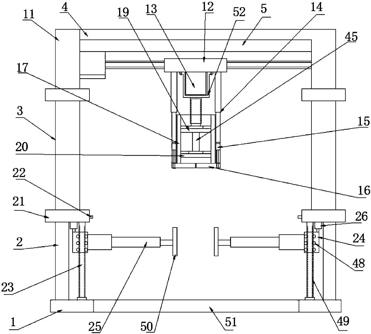
[0028] Such as Figure 1-5As shown, the suction barrel guide frame with high installation efficiency according to the embodiment of the present invention includes a horizontal plate-1, and a support rod-2 is symmetrically provided on both sides of the top of the horizontal plate-1, and the top of the support rod-2 Mounting seats 21 are provided, and infrared sensors 22 are provided on the corresponding sides adjacent to the mounting seats 21, and the two sides of the top of the horizontal plate-1 are provided with a limit position between the adjacent support rods-2. Rod 23, the limit rod 23 is connected with the bottom end of the mounting seat 21, the limit rod 23 is provided with a movable seat 24, the top of the movable seat 24 is arranged on the bottom of the mounting seat 21 The electric telescopic rod one 26 at the end is connected, and the corresponding side of the adjacent movable seat 24 is provided with a clamping mechanism, and the top of the mounting base 21 is pro...

Embodiment 2

[0031] Such as figure 1 , 5 As shown, the two adjacent support rods 11 and the second horizontal plate 4 are integrally formed, and the two support rods 11 and the second horizontal plate 4 form an inverted U-shaped structure, and the first swing plate 36 and the second swing plate 37 are arranged symmetrically about the center. The support rod 2 11 and the horizontal plate 2 4 form an inverted U-shaped structure, which is convenient for fixing the mounting plate 5 .

[0032] Such as Figure 5 As shown, the second fixed box 33 is a circular structure, the first fixed box 27 is a rectangular structure, and both sides of the second fixed box 33 are provided with through grooves 39 that are compatible with the clamping plate 38 . Through the provided through slot 39 , the movement of the clamping plate 38 is facilitated, thereby realizing the clamping of the suction barrel 17 .

[0033] Such as Figure 5 As shown, the side of the swing plate 2 37 close to the swing plate 36...


PUM


Abstract

The invention discloses a suction bucket guide frame with high mounting efficiency. The suction bucket guide frame comprises a first horizontal plate, first supporting rods are symmetrically arrangedon two sides of the top end of the first horizontal plate, mounting seats are arranged at the top ends of the first supporting rods, infrared sensors are arranged on corresponding side faces of adjacent first mounting seats, limit rods positioned between the adjacent first supporting rods are arranged on two sides of the top end of the first horizontal plate and connected with the bottom ends of the mounting seats, movable seats sleeve the limit rods, the top ends of the movable seats are connected with first electric telescopic rods arranged at the bottom ends of the first mounting seats, clamping mechanisms are arranged on corresponding side faces of the adjacent movable seats, and fourth electric telescopic rods and second supporting rods positioned on the fourth electric telescopic rods are arranged at the top ends of the mounting seats. The suction bucket guide frame has the advantages that the inside of a suction bucket is effectively clamped and fixed by the aid of the first clamping mechanism and the second clamping mechanism, operation safety of the suction bucket is improved, falling of the suction bucket is effectively avoided, and resources are saved.

Description

technical field [0001] The invention relates to the technical field of construction, in particular to a suction barrel guide frame with high installation efficiency. Background technique [0002] During the construction of the highway bridge, the verticality of the pile foundation suction barrel sinking and the deviation of the center position directly affect whether the pile can be successfully formed and the quality of the pile foundation construction, and affect the lowering of the steel suspension box of the cap. The traditional suction bucket guide frame is a cantilever type guide frame, and must be positioned on the platform for construction. On the one hand, the hoisting height of the door crane is required to be greater; The vibration will cause the suction barrel to shift, which will cause the installation of the suction barrel to be misplaced, resulting in the failure of the installation of the suction barrel, which will lead to low construction efficiency. [000...

Claims


Application Information

Patent Timeline
IPC IPC(8): E02D13/04
CPCE02D13/04
Inventor 严志兵
Owner 江苏长风海洋装备制造有限公司
Features
  • Generate Ideas
  • Intellectual Property
  • Life Sciences
  • Materials
  • Tech Scout
  • Unparalleled Data Quality
  • Higher Quality Content
  • 60% Fewer Hallucinations
Learn More