Pipeline leakage detection device

A detection device and pipeline leakage technology, which is applied in pipeline systems, mechanical equipment, gas/liquid distribution and storage, etc., and can solve problems such as toxicity, danger, and leakage

Active Publication Date: 2019-04-19
WENZHOU VOCATIONAL COLLEGE OF SCI & TECH
View PDF10 Cites 5 Cited by
  • Summary
  • Abstract
  • Description
  • Claims
  • Application Information

AI Technical Summary

Problems solved by technology

[0002] In the current chemical plant, raw materials are often transmitted through pipelines, and flanges, valves and other components are often connected between pipelines. Flanges serve as the connection between pipelines, and valves play the role of The control of the fluid in

Method used


Image

  • Pipeline leakage detection device
  • Pipeline leakage detection device

Examples


specific Embodiment approach

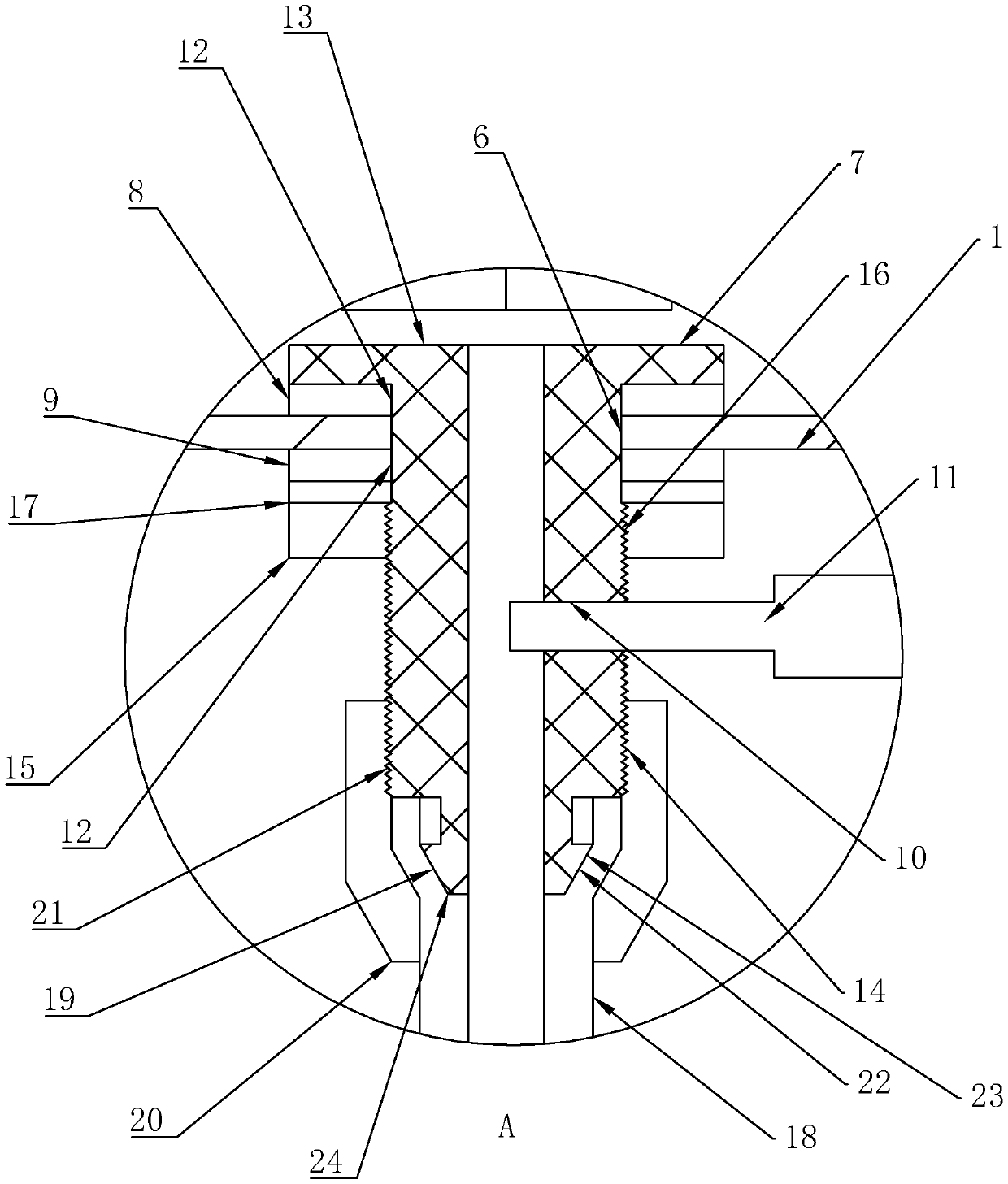
[0036] The first clamping member 8 and the second clamping member 9 are rubber blocks, and both are provided with a through hole 12 for the vacuum tube 7 to pass through.

[0037] Through the above technical solution, rubber blocks are used in the selection of the first clamping member 8 and the second clamping member 9. Through the interference fit of the rubber blocks, the rubber blocks are deformed and the protective cover 1 is better clamped. Improve the sealing effect on the through hole 6.

[0038] As a specific implementation of improvement,

[0039] An end of the vacuum tube 7 located in the sealed space 5 is provided with a resisting disk 13, and the first clamping member 8 is located between the resisting disk 13 and the protective cover 1.

[0040] Through the above technical solution, through the arrangement of the resisting disc 13, it can be possible that the first clamping member 8 can be resisted by the resisting disc 13, so as to have a supporting force for the first ...


PUM


Abstract

The invention discloses a pipeline leakage detection device. The pipeline leakage detection device comprises a protection cover and a pipeline assembly, the pipeline assembly is located in the protection cover, the protection cover is provided with an opening, the opening and the pipeline assembly form a sealing space, a through hole is formed in the protective cover, a vacuum tube penetrates through the through hole, a first clamping piece is arranged at the end, located in the sealing space, of the vacuum tube, a second clamping piece is arranged at the end, located outside the sealing space, of the vacuum tube, the first clamping piece and the second clamping piece are used for clamping the protective cover and enabling the through hole to be in a sealed state, a detection opening is formed in the end, extending out of the sealing space, of the vacuum tube, a detection element is arranged in the detection opening, and a control valve is arranged at the end, opposite to the detectionopening and the through hole, of the vacuum tube. Once leakage occurs, leaked material enters the vacuum tube due to the fact that the sealing space is in a negative pressure state, leakage can be detected according to the detection element, so that whether the pipeline assembly leaks or not can be detected.

Description

Technical field [0001] The invention relates to the field of safe production, more specifically to a pipeline leak detection device. Background technique [0002] In the current chemical plant, raw materials are often transferred through pipelines. There are often flanges, valves and other components connected between the pipeline and the pipeline. The flange acts as the connection between the pipeline and the pipeline, and the valve acts as the connection between the pipeline and the pipeline. The control of the fluid in the pipeline, but the flange or valve or even the pipeline itself is prone to leakage. Many raw materials in chemical plants, including liquids, gases and even solids, are toxic. Once the leakage is not detected in time, it will cause great danger. Summary of the invention [0003] In view of the deficiencies in the prior art, the purpose of the present invention is to provide a pipeline leak detection device. [0004] In order to achieve the above objective, the...

Claims


Application Information

Patent Timeline
IPC IPC(8): F17D5/02
CPCF17D5/02
Inventor 姜军徐谦
Owner WENZHOU VOCATIONAL COLLEGE OF SCI & TECH
Why Eureka
Try Eureka