Magnetic buckle

A magnetic and magnet technology, applied in the field of magnetic hasp, can solve the problems of not conforming to daily use habits, inconvenient operation, and the aesthetics needs to be improved, so as to achieve the requirements of reducing the magnetic attraction, reducing the magnetic strength, and reducing the opening force. Effect

Pending Publication Date: 2019-04-23
LIAN YANG PLASTIC (SHEN ZHEN) CO LTD
View PDF0 Cites 10 Cited by
  • Summary
  • Abstract
  • Description
  • Claims
  • Application Information

AI Technical Summary

Problems solved by technology

This kind of magnetic buckle needs to be pressed hard when it is unlocked. It either needs to be operated by both hands to unlock it, or it will apply the pressing force to the occupant, and it is unlocked by lifting it up. It needs to overcome the magnetic force when lifting it. It can only be unlocked by pulling up with a large force, so its actual operation is not convenient and laborious
[0005] Another conventional unlocking method is to dislocate the magnet by sliding and then separate the buckle. On the one hand, this kind of magnetic buckle needs to provide space for the magnet to displace, so its volume is large and its aesthetics needs to be improved; On the one hand, the pressing unlocking method is most familiar to the public in daily life, and the operation method of dislocating the magnet by sliding does not conform to the daily use habits of the public to unlock. For first-time users, it is difficult to know how to unlock. Therefore, There may be security risks in some scenarios
[0006] To sum up, although the existing magnetic buckle is convenient to lock, its unlocking method still needs to be improved, so as to be more in line with the daily habits of the public, and more labor-saving and easy to operate

Method used


Image

  • Magnetic buckle
  • Magnetic buckle
  • Magnetic buckle

Examples


Embodiment Construction

[0027] The following examples are further explanations and supplements to the present invention, and do not constitute any limitation to the present invention.

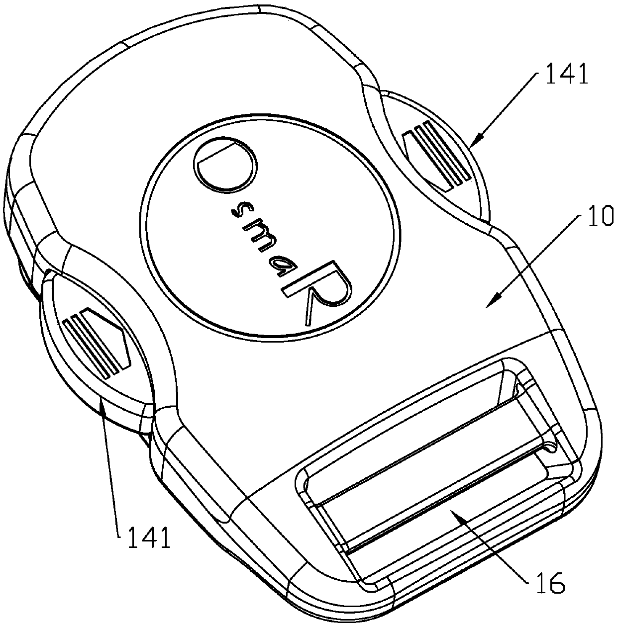
[0028] Such as Figure 1 to Figure 6 As shown, the main point of the magnetic buckle of the present invention is to press both sides to unlock it. When pressing, the unlocking part 142 inside it can be inserted between the two parts attracted by the magnet to separate them, so as to weaken the magnet. The magnetic force can be easily unlocked.

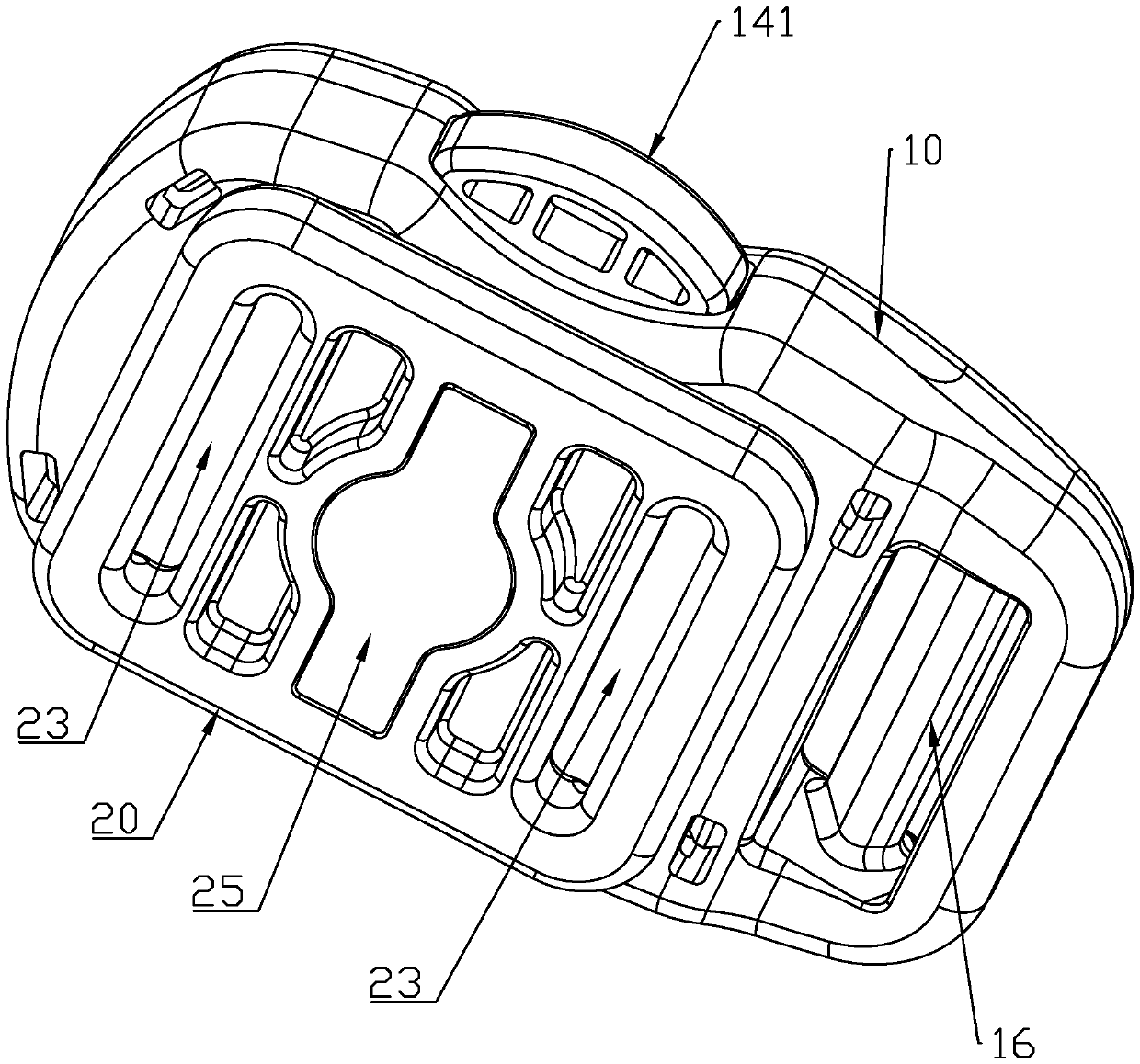
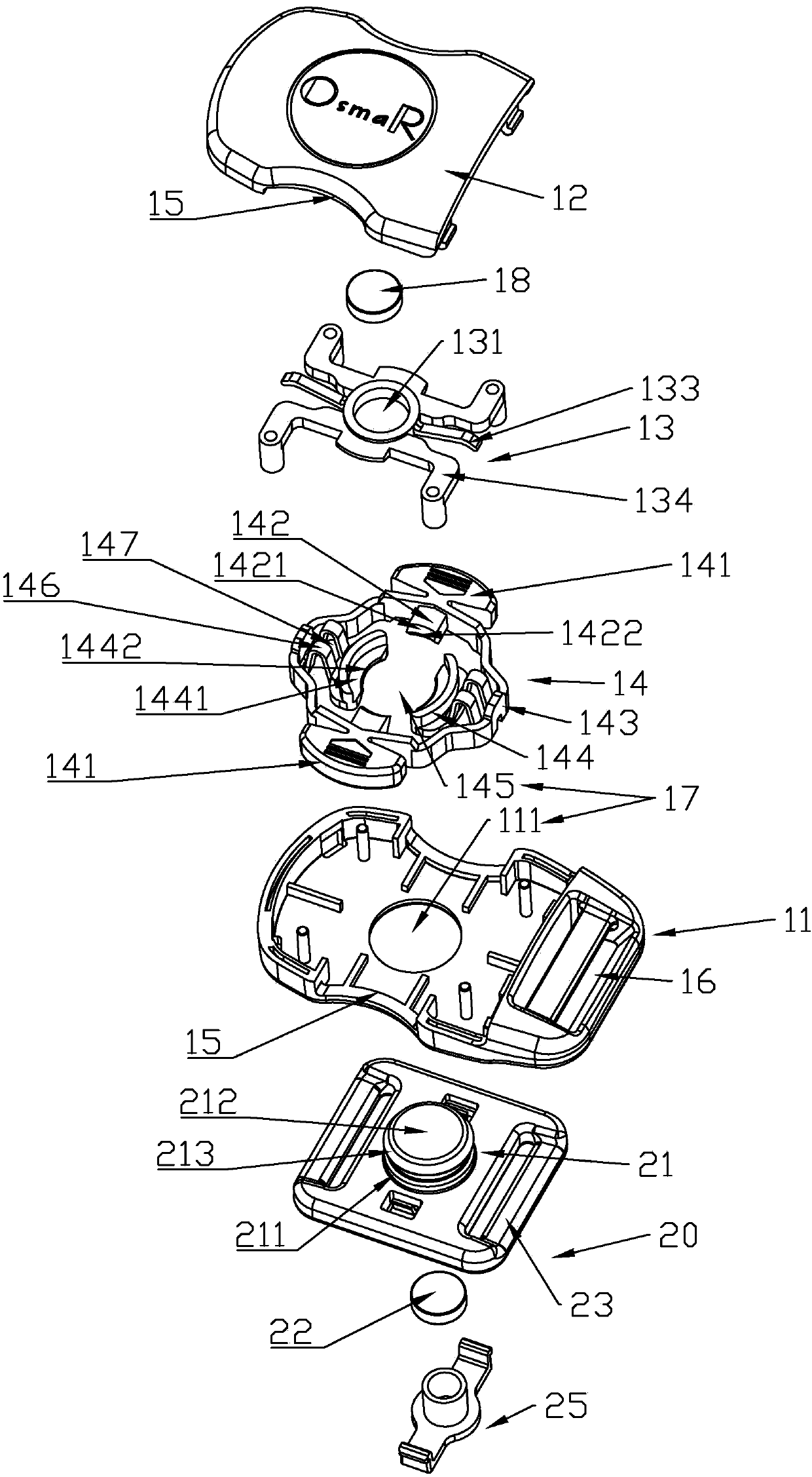
[0029] Specifically, such as Figure 4 As shown, the magnetic buckle of the present invention includes a buckle seat component 10 and a lock component 20 .

[0030] Such as Figure 1 to Figure 6 As shown, the buckle seat assembly 10 includes a base 11 , an upper cover 12 , a magnet fixing seat 13 and a button linkage 14 .

[0031] Such as Figure 1 to Figure 6As shown, the base 11 and the upper cover 12 are engaged and connected, and an installation space is formed thereb...


PUM


Abstract

A magnetic buckle comprises a buckle seat assembly and a lock catch assembly, wherein a first magnet is arranged in the buckle seat assembly, a lock hole corresponding to the first magnet is formed inone side of the buckle seat assembly, facing the lock catch assembly, the size of the lock hole is adjustable, a lock bolt capable of being inserted into the lock hole is arranged on one side of thelock catch assembly, facing the buckle seat assembly, a second magnet corresponding to the lock bolt is arranged in the lock catch assembly, pressing parts are respectively arranged on two opposite sides of the buckle seat assembly, an unlocking part linked by the pressing parts is arranged in the buckle seat assembly, and the unlocking part faces the lock hole; when the lock hole of the buckle seat assembly is close to the lock bolt of the lock catch assembly, the first magnet and the second magnet attract each other to guide the lock bolt in entering the lock hole so as to achieve locking; when the pressing parts are pressed oppositely, the unlocking part moves towards the combined parts of the lock bolt and the buckle seat assembly so as to space the combined parts of the lock bolt andthe buckle seat assembly and reduce the attraction force between the first magnet and the second magnet so as to facilitate the separation of the buckle seat assembly and the lock catch assembly.

Description

【Technical field】 [0001] The invention relates to a buckle, in particular to a magnetic buckle which is easy to operate and conforms to ergonomics. 【Background technique】 [0002] Some parts of children's products such as strollers, child safety seats, and baby carriers usually need to be connected or maintained in a certain state through buckles. Fasteners are used to realize this variable state connection. Usually, most of the buckles are plug-in safety buckles, which require the user to use both hands to align and lock the mating male buckle and the female buckle to achieve a safe connection. But in reality, users often need to hold the child in one hand and operate the safety buckle with the other. Therefore, this plug-in safety buckle is inconvenient to operate and cannot meet the needs of various scenarios. Therefore, magnetic buckles are gradually used. Buckle to solve this problem. [0003] A magnetic buckle is a buckle that is locked by magnetic force. It usually...

Claims


Application Information

Patent Timeline
Patent Type & Authority Applications(China)
IPC IPC(8): A44B11/25
CPCA44B11/2557A44B11/2573
Inventor 李邱宗
Owner LIAN YANG PLASTIC (SHEN ZHEN) CO LTD
Why Eureka
Try Eureka