Steel hoisting frame

A lifting frame and steel technology, which is applied to portable lifting devices, hoisting devices, etc., can solve the problems of difficulty in moving and hoisting equipment, time-consuming and laborious, and achieve the effect of small occupied space, convenient use, and convenient movement and hoisting.

Inactive Publication Date: 2019-04-23
丹阳市俊腾五金有限公司
View PDF0 Cites 0 Cited by
  • Summary
  • Abstract
  • Description
  • Claims
  • Application Information

AI Technical Summary

Problems solved by technology

However, due to many reasons such as the early construction of the factory area and the space limitation in the later stage, the existing hoisting equipment such as cranes and forklifts cannot meet the existing conditions of use. As a result, hoisting equipment such as mobile cranes and forklifts cannot enter, and the movement and hoisting of equipment are more difficult, which is not only time-consuming and laborious, but also extremely dangerous

Method used


Image

  • Steel hoisting frame

Examples


Embodiment Construction

[0011] The preferred embodiments of the present invention are given below in conjunction with the accompanying drawings to describe the technical solution of the present invention in detail.

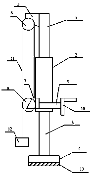
[0012] Such as figure 1 Shown, a kind of steel lifting frame, it comprises ejector rod 1, fixed rod 2, bottom rod 3, base 4, first roller holder 5, first roller 6, second roller holder 7, second roller 8, Transmission shaft 9, rocker 10, transmission line 11, lifting end 12 and crawler belt 13, the top rod 1 is installed above the fixed rod 2, the bottom rod 3 is installed under the fixed rod 2, the bottom rod 3 is connected with the base 4, and the crawler belt 13 is installed Below the base 4, the first roller 6 is installed on the first roller holder 5, the first roller holder 5 is connected with the push rod 1, the second roller 8 is installed on the second roller holder 7, and the transmission shaft 9 is connected to the rocker The rod 10 is connected to the second roller fixer 7 ,...


PUM


Abstract

The invention discloses a steel hoisting frame. The steel hoisting frame comprises an ejector rod, a fixing rod, a bottom rod, a base, a first roller fixer, a first roller, a second roller fixer, a second roller, a transmission shaft, a rocker, a transmission line, a hoisting end and a crawler, wherein the ejector rod is arranged above the fixing rod, the bottom rod is arranged below the fixing rod, the bottom rod is connected with the base, the crawler is arranged below the base, the transmission shaft is connected with the rocker and the second roller fixer, and the hoisting end is connectedwith the transmission line. According to the steel hoisting frame, the steel is lifted by adopting the matching of a vertical column and a sliding sleeve, the problem that the steel to be hoisted isdifficult to move and hoist under the condition that without hoisting equipment or hoisting equipment such as cranes are not hoisted in the prior art is solved, when the steel hoisting frame is movedand hoisted, the steel hoisting frame can be moved and hoisted rapidly and conveniently, is convenient and reliable to use and small in occupied space and can be used in a narrow space.

Description

technical field [0001] The invention relates to a lifting frame, in particular to a steel lifting frame. Background technique [0002] In the current production, it is often necessary to move steel materials such as motors and pumps from one place to another. At present, cranes and forklifts are often used for lifting and moving large-scale equipment. However, due to many reasons such as the early construction of the factory area and the space limitation in the later stage, the existing hoisting equipment such as cranes and forklifts cannot meet the existing conditions of use. As a result, hoisting equipment such as mobile cranes and forklifts cannot enter, and the movement and hoisting of equipment are more difficult, which is not only time-consuming and laborious, but also extremely dangerous. Therefore, a solution is needed to solve the above problems. Contents of the invention [0003] The technical problem to be solved by the present invention is to provide a steel ...

Claims


Application Information

Patent Timeline
Patent Type & Authority Applications(China)
IPC IPC(8): B66D3/14
CPCB66D3/14B66D2700/0183
Inventor 戎潇俊
Owner 丹阳市俊腾五金有限公司
Why Eureka
Try Eureka