Curved surface laminating jig and laminating equipment

A technology for fitting fixtures and curved surfaces, applied in the direction of layered products, lamination devices, lamination, etc., can solve the problems of high cost of use, easy damage to the flexible cavity wall, etc., to improve the service life, reduce deformation, and reduce replacement. effect of times

Active Publication Date: 2019-04-26
BOE TECH GRP CO LTD +1
View PDF3 Cites 16 Cited by
  • Summary
  • Abstract
  • Description
  • Claims
  • Application Information

AI Technical Summary

Problems solved by technology

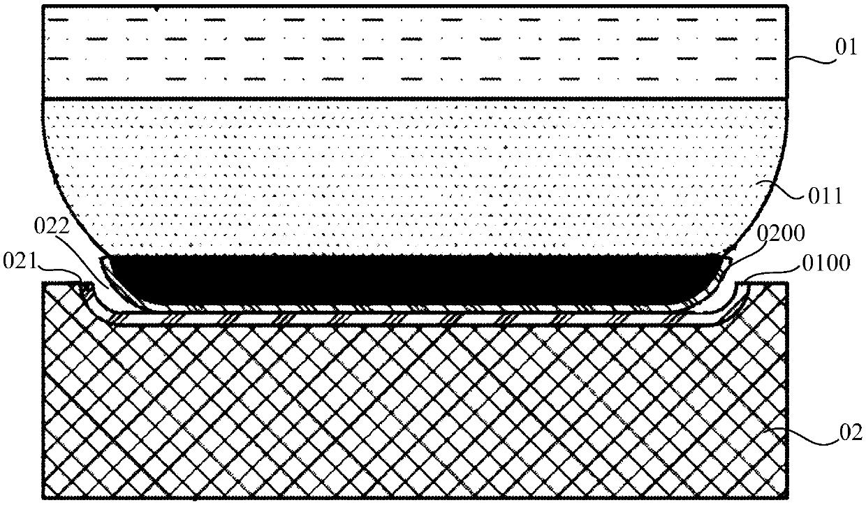
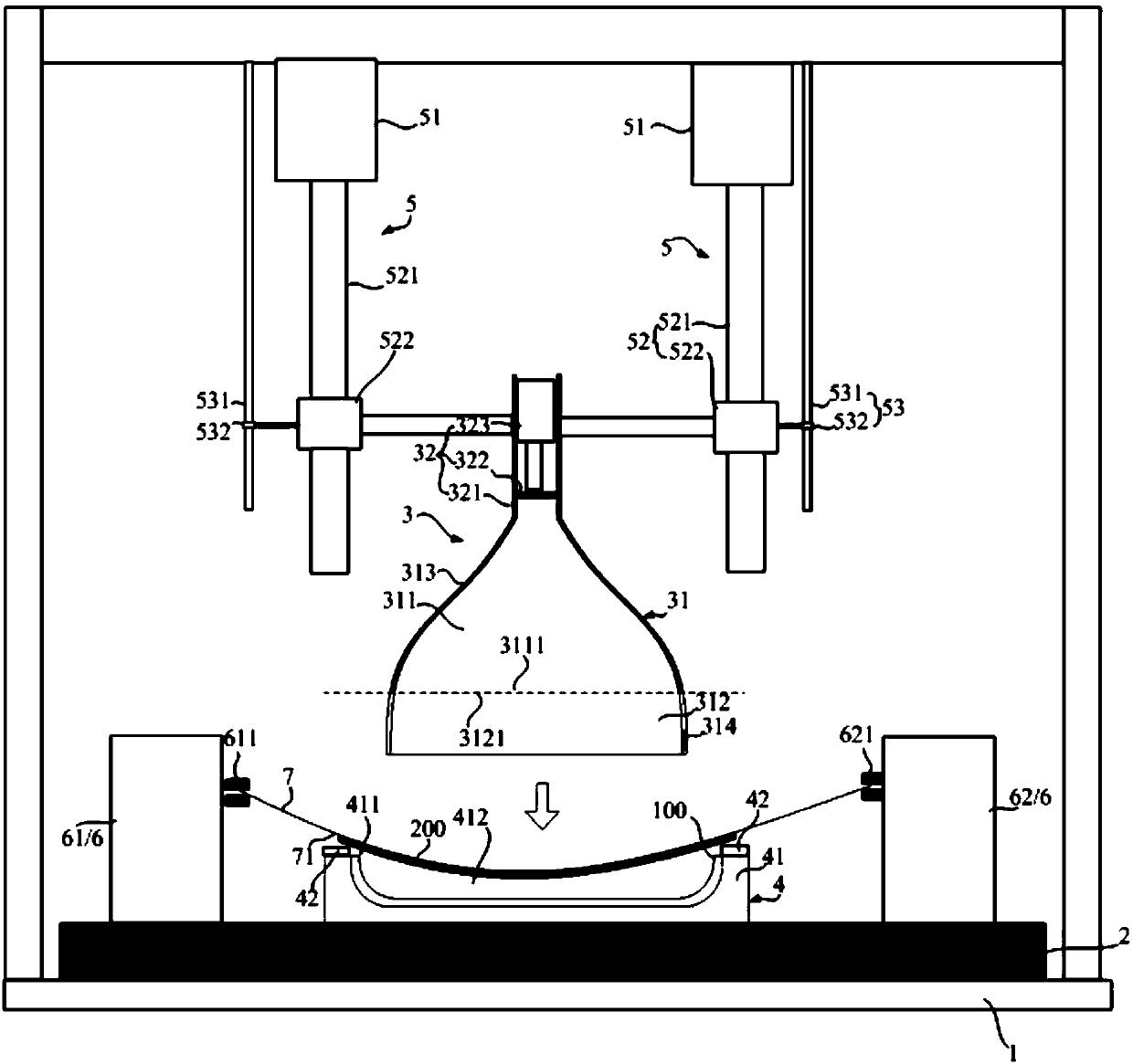
[0005] The embodiment of the present invention provides a curved surface laminating fixture and laminating equipment, which are used to solve the problem that the flexible cavity wall in the upper fixture of the curved surface laminating fixture is easily damaged in the related art, resulting in high cost of use

Method used


Image

  • Curved surface laminating jig and laminating equipment
  • Curved surface laminating jig and laminating equipment
  • Curved surface laminating jig and laminating equipment

Examples


Embodiment Construction

[0022] The following will clearly and completely describe the technical solutions in the embodiments of the present invention with reference to the accompanying drawings in the embodiments of the present invention. Obviously, the described embodiments are only some, not all, embodiments of the present invention. Based on the embodiments of the present invention, all other embodiments obtained by persons of ordinary skill in the art without making creative efforts belong to the protection scope of the present invention.

[0023] In describing the present invention, it is to be understood that the terms "center", "upper", "lower", "front", "rear", "left", "right", "vertical", "horizontal", The orientations or positional relationships indicated by "top", "bottom", "inner", "outer", etc. are based on the orientations or positional relationships shown in the drawings, and are only for the convenience of describing the present invention and simplifying the description, rather than in...


PUM


Abstract

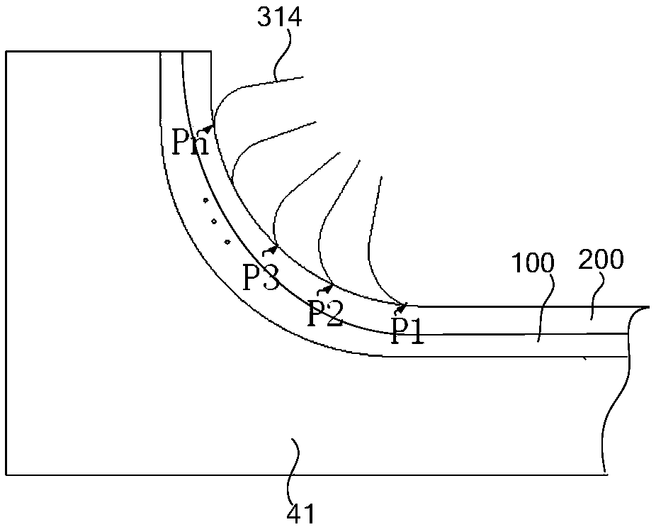
The invention discloses a curved surface laminating jig and laminating equipment, relates to the technical field of curved surface lamination and aims to solve the problem of relatively high use costof the curved surface laminating jig as a flexible cavity wall in an upper jig in a curved surface laminating jig in the related art is easy to break. The curved surface laminating jig comprises a stand, a supporting table, an upper jig, a lower jig and a driving device, wherein the lower jig is arranged on the supporting table; the lower jig is provided with a placement cavity with a placement opening; the upper jig comprises a press-fit cavity; the press-fit cavity comprises a first sub cavity encircled by a rigid cavity wall and a second sub cavity encircled by a flexible cavity wall; the first sub cavity is provided with a first downward opening, and the second sub cavity is provided with a second upward opening; the second opening is hermetically abutted with the first opening; fluidis fed into both the first sub cavity and the second sub cavity; under the driving of the driving device, the supporting table and the upper jig can move relatively in a vertical direction. The curvedsurface laminating jig disclosed by the invention can be used for laminating a flexible panel and a curved cover plate.

Description

technical field [0001] The invention relates to the technical field of curved surface bonding, in particular to a curved surface bonding fixture and bonding equipment. Background technique [0002] The display screen is divided into a flat display screen and a curved display screen. Since the picture produced by the curved display is not easy to be distorted, the display gradually enters a new era of curved shape. One of the manufacturing processes of the curved display is to attach the flexible display panel to the curved cover. The above-mentioned lamination process is carried out on the curved surface lamination jig of the laminating equipment. How to design the curved surface lamination jig is an important issue in the industry the goal that is pursued. [0003] A curved surface bonding fixture in the related art, such as figure 1 As shown, it includes an upper jig 01 and a lower jig 02. The lower jig 02 has a placement cavity 022 with an opening 021. The placement ca...

Claims


Application Information

Patent Timeline
Patent Type & Authority Applications(China)
IPC IPC(8): B32B37/10
CPCB32B37/10B32B37/1009
Inventor 谭森雷嗣军李登仟
Owner BOE TECH GRP CO LTD
Why Eureka
Try Eureka