
Equipment used for changing grounding wire to be spiral

A helical, wire-connecting technology, applied in the field of wire-connecting and winding tools and equipment, can solve the problems of easy damage to winding rods and grounding wires, and achieve the effect of reducing production costs

Active Publication Date: 2019-04-26
STATE GRID CORP OF CHINA +1
View PDF12 Cites 10 Cited by
  • Summary
  • Abstract
  • Description
  • Claims
  • Application Information

AI Technical Summary

Problems solved by technology

[0004] The present invention provides a device for turning the connecting wire into a spiral shape, which solves the problem in the prior art that the winding rod needs to be pulled to move in a direction parallel to the centerline of the winding reel due to the need to pull the grounding wire and the relative winding rod. and the problem that the ground wire is easily damaged

Method used


Image

  • Equipment used for changing grounding wire to be spiral
  • Equipment used for changing grounding wire to be spiral
  • Equipment used for changing grounding wire to be spiral

Examples


Embodiment Construction

[0014] In order to make the technical means, creative features, goals and functions achieved by the present invention clearer and easier to understand, the present invention will be further elaborated below in conjunction with the accompanying drawings and specific embodiments:

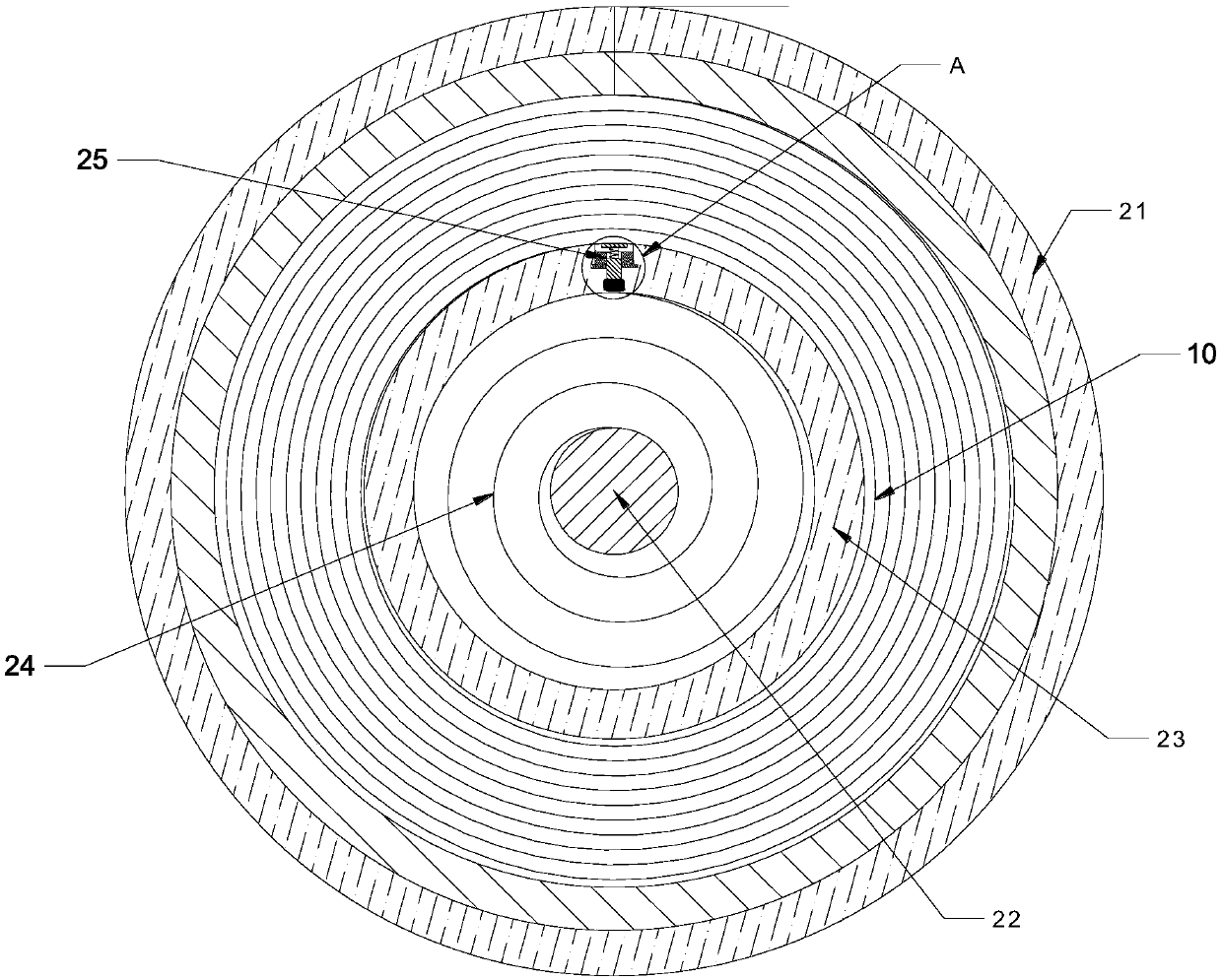
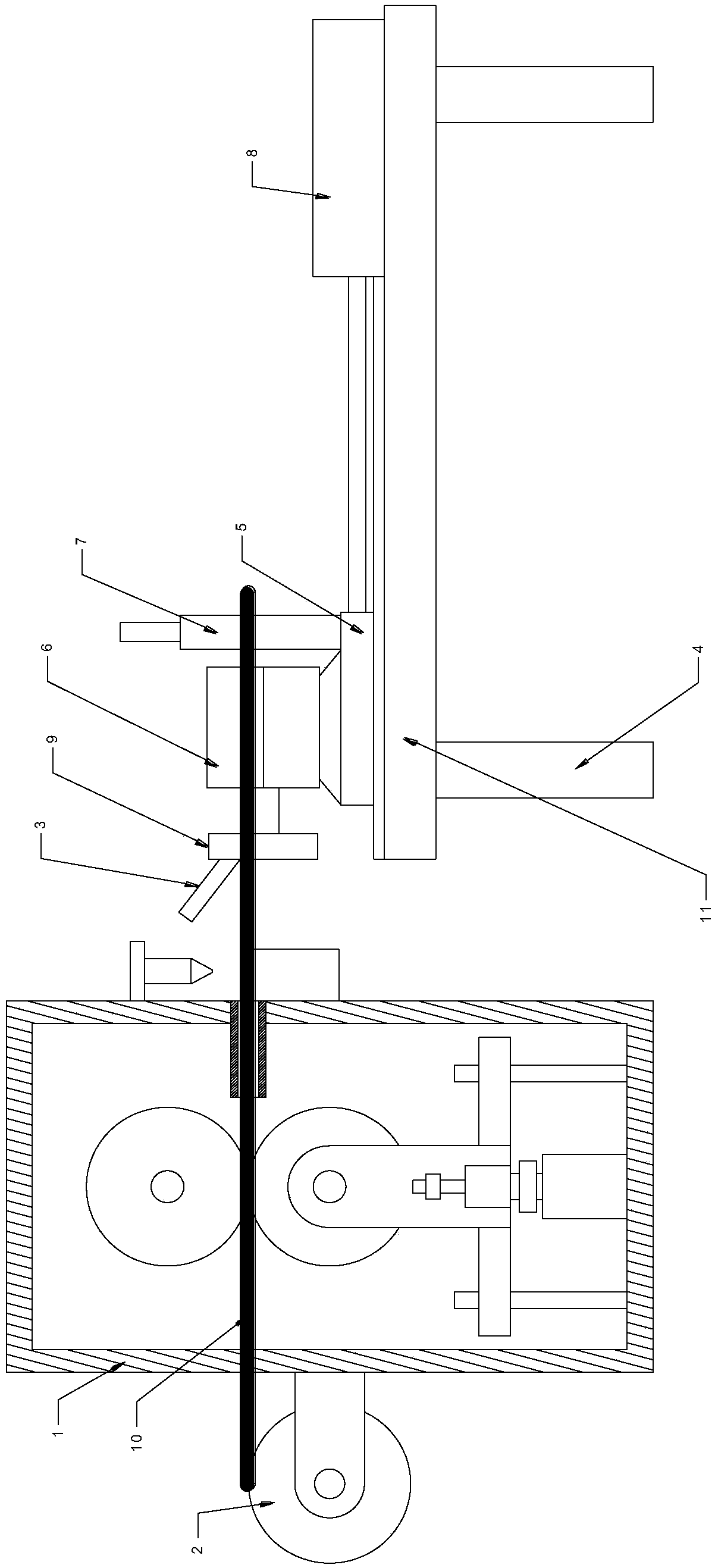
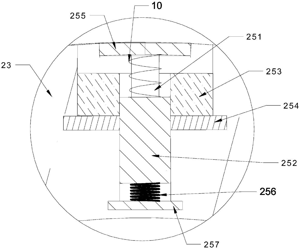
[0015] Such as Figure 1 to Figure 3 As shown, the present invention proposes a device for turning the connecting wire into a spiral shape, including: a first frame 1, a convolution device 2, a winding rod 3, a second frame 4, a sliding seat 5, a rotating drive Device 6, clamping device 7 (its structure can be the same as the prior art) and horizontal driving device 8, the coiling device 2 that is used for convolution ground wire 10 is installed on the first frame 1 side, on the first frame 1. The second frame 4 is installed on the other side, and a support platform 11 is installed on the second frame 4. A sliding seat 5 capable of sliding is installed on the support platform 11. A rotary drive device...


PUM


Abstract

The invention provides equipment used for changing a grounding wire to be spiral. The equipment comprises a first rack, a convoluting device, a winding rod, a second rack, a sliding seat, a rotary driving device, a clamping device and a horizontal driving device. The convoluting device used for convoluting the grounding wire is mounted on one side of the first rack. A supporting table is mounted on the second rack. The sliding seat capable of sliding is mounted on the supporting table. The rotary driving device is mounted on the sliding seat. The output end of the rotary driving device is connected to a rotary disc. The winding rod is mounted on the rotary disc. The clamping device is mounted on the sliding seat and used for clamping the end, away from the convoluting device, of the grounding wire. The horizontal driving device is mounted on the side, away from the convoluting device, of the sliding seat. By means of the equipment used for changing the grounding wire to be spiral, theproblems that during winding in the prior art, a grounding wire needs to be pulled and moves in the direction parallel to a central line of a wire spool relative to a winding rod, and consequentially,the winding rod and the grounding wire are prone to being damaged are solved.

Description

technical field [0001] The invention relates to a tool device for wire winding, in particular to a device for turning the wire into a spiral shape. Background technique [0002] Chinese patent discloses a grounding wire winder with application number CN201410280264.7, which includes a first frame, an upper wheel, a lower wheel, a lower wheel lifting assembly, a second frame, and a clamping assembly , a winder and a cutting knife, the first frame is a square cavity structure, a first ear plate is fixed on the left side wall of the first frame, and a first ear plate is fixedly installed on the first ear plate Fixed shaft; extending upward from the bottom of the first frame two guide columns arranged on the left and right sides, a lift platform is slidably installed on the two guide columns, and a mounting plate is vertically fixedly installed on the front and rear sides of the lift platform respectively , a lead screw nut is fixedly installed at the bottom of each of the moun...

Claims


Application Information

Patent Timeline
Patent Type & Authority Applications(China)
IPC IPC(8): B65H54/54B65H49/20B65H54/44
CPCB65H49/20B65H54/44B65H54/54B65H2701/34
Inventor 汪小东王东余佳胡开洪张智吴勇赵川
Owner STATE GRID CORP OF CHINA
Learn More