Wind-driven retrograde motion driving mechanism

A technology of driving mechanism and actuator, applied in the field of machinery, can solve the problem of less energy-saving improvement technology and so on

Inactive Publication Date: 2019-04-26
徐明秋
View PDF3 Cites 0 Cited by
  • Summary
  • Abstract
  • Description
  • Claims
  • Application Information

AI Technical Summary

Problems solved by technology

[0009] The purpose of the present invention is to provide a wind power retrograde drive mechanism, which can solve the defect that the existing wind power energy-saving equipment is only used outdoors to realize wind power generation, and there are few energy-saving improvement technologies applied to other fields

Method used


Image

  • Wind-driven retrograde motion driving mechanism
  • Wind-driven retrograde motion driving mechanism

Examples


Embodiment 1

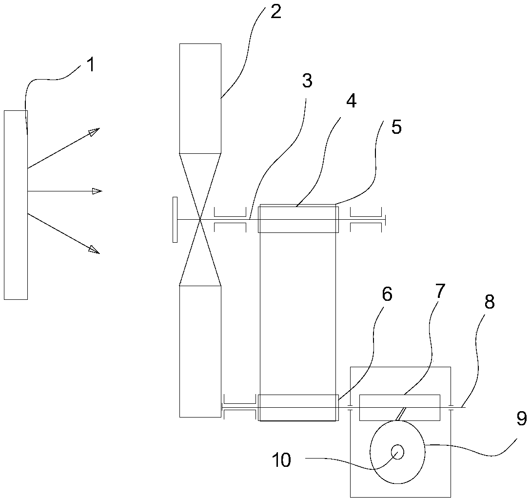
[0028] Such as figure 1 As shown, the driving mechanism includes fan blade 2, fan shaft 3, transmission device, reducer and actuator, fan blade 2 is fixedly connected to fan shaft 3, fan shaft 3 is connected with transmission device, and fan shaft 3 drives the transmission device to exert force on The speed reducer, the shaft of the speed reducer is connected to the actuator, and the power source of the driving mechanism is natural wind or artificial wind.

[0029] The driving mechanism is connected to the unpowered trolley, and the power source can be a fan or other mechanism, and the self-running of the driving mechanism can be realized by turning on the fan. It faces the fan blade in front of the wind force, and the wind acts on the fan blade to generate thrust on the fan blade 2, the fan blade rotates, the fan blade 2 is fixedly connected to the fan shaft, and the fan blade 2 drives the fan shaft 3 to rotate, and the fan shaft 3 To transmit the rotational force to the tra...

Embodiment 2

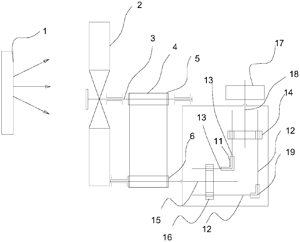
[0040] Such as figure 2 shown, with figure 1 Part of the structure is the same, and the driving mechanism of the specific embodiment 2 includes the fan blade 2, the fan shaft 3, the transmission device, the reducer and the actuator, the fan blade is fixedly connected to the fan shaft 3, the fan shaft 3 is connected to the transmission device, and the fan shaft 3 Drive the transmission device to apply force to the reducer, and the reducer shaft is connected to the actuator. The power source of the drive mechanism is natural wind or artificial wind, and the movement direction of the actuator is opposite to the direction of the wind force. The power source can consider choosing an electric fan. The executive structure is the wheel, which can be used as the rear wheel of the trolley. When the electric fan is turned on, the driving mechanism is driven by the wind to move forward, and the wheels move forward.

[0041] This mechanism can also be applied to outdoor scenes. When t...


PUM


Abstract

The invention provides a wind-driven retrograde motion driving mechanism. The driving mechanism comprises fan blades, a fan shaft, a transmission device, a speed reducer and an executing mechanism; the fan blades are fixedly connected to the fan shaft; the fan shaft is connected with the transmission device and is used for driving the transmission device to apply force to the speed reducer; a rotating shaft of the speed reducer is connected with the executing mechanism; and the power source of the driving mechanism is natural wind or artificial wind. The wind-driven retrograde motion driving mechanism related to the invention can also realize equipment running of the driving mechanism in a room as long as a wind source is provided.

Description

technical field [0001] The invention belongs to the technical field of machinery, and in particular relates to a wind force retrograde drive mechanism. Background technique [0002] As the main power source of energy saving projects, wind power has matured in our country. Especially the use of wind power. However, there are few structural improvements or method improvements for applying wind power energy-saving technology to other industries. [0003] A device that relies on wind power to achieve driving force has been disclosed. The device is equipped with blades, wind power transmission rods, solar power generation devices, dual-purpose motors for power generation, gear transmission mechanisms, batteries, rectifier circuits, switch control circuits, and blades. On the top of the wind power transmission rod, a bearing is installed on the wind power transmission rod, and a gear is fixed on the outer ring of the bearing. The upper part of the gear is provided with a three-p...

Claims


Application Information

Patent Timeline
Patent Type & Authority Applications(China)
IPC IPC(8): F03D9/11F03D9/32F03D15/00F03D1/06
CPCF03D1/065F03D9/11F03D9/32F03D15/00Y02E10/72Y02E10/728Y02E70/30
Inventor 徐明秋
Owner 徐明秋
Why Eureka
Try Eureka