Differential ratchet type anti-loosening double nut

A double nut and ratchet technology, applied in the direction of nuts, screws, bolts, etc., can solve the problems of difficult processing, complex structure, unable to prevent the relative rotation of double nuts, etc., and achieve the effect of improving the anti-loosening effect and simple installation process.

Active Publication Date: 2019-04-26
杨天啸
View PDF6 Cites 1 Cited by
  • Summary
  • Abstract
  • Description
  • Claims
  • Application Information

AI Technical Summary

Problems solved by technology

[0002] Nuts are widely used. In some vibration or important occasions, anti-loosening technology is required. Double nut anti-loosening is a widely used technology. However, in some more important or strong vibration occasions, ordinary double nuts still cannot achieve satisfactory results. Anti-loose effect
There are many improved double nut technologies in the prior art, such as double nuts with eccentric sleeves and double nuts with tightening structure. The principle is basically to increase friction to prevent loosening. It still cannot prevent the relative rotation between the double nuts, and there are disadvantages such as complex structure, difficult processing, and high precision requirements for the matched screw.

Method used


Image

  • Differential ratchet type anti-loosening double nut
  • Differential ratchet type anti-loosening double nut
  • Differential ratchet type anti-loosening double nut

Examples


Embodiment 1

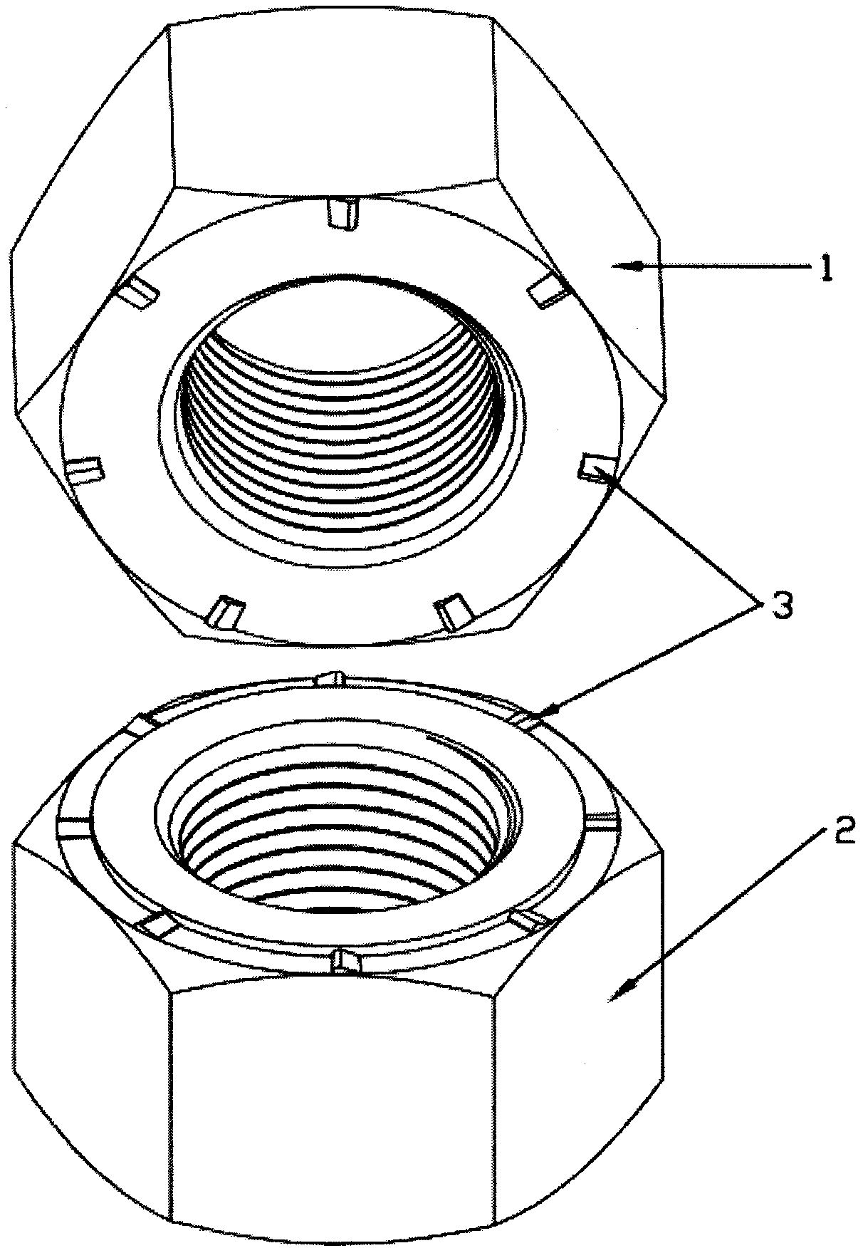
[0014] Such as figure 1 As shown, taking the M30 nut as an example, the upper nut has 7 ratchets, the lower nut has 8 ratchets, the ratchets are set on the end surface of the nut, the ratchets of the upper nut are set Located on the upper end face, each ratchet occupies less than one fifty-sixth of a circle in the circumferential direction, the tooth height is about 1mm, the tooth width is about 3mm, and the top of the tooth has rounded corners. The ratchet direction of the upper and lower nuts is easy Tighten, difficult to unscrew. When installing, tighten the lower nut first, and then screw the upper nut. When the end faces of the upper nut and the lower nut come into contact, a group of ratchets will start to bear force and cause resistance to tightening the upper nut. Further increase the tightening torque. Due to the elastic deformation of the nut and the bolt With the existence of the ratchet, this group of ratchets will cross and mesh with each other, and every 1 / 56th ...

Embodiment 2

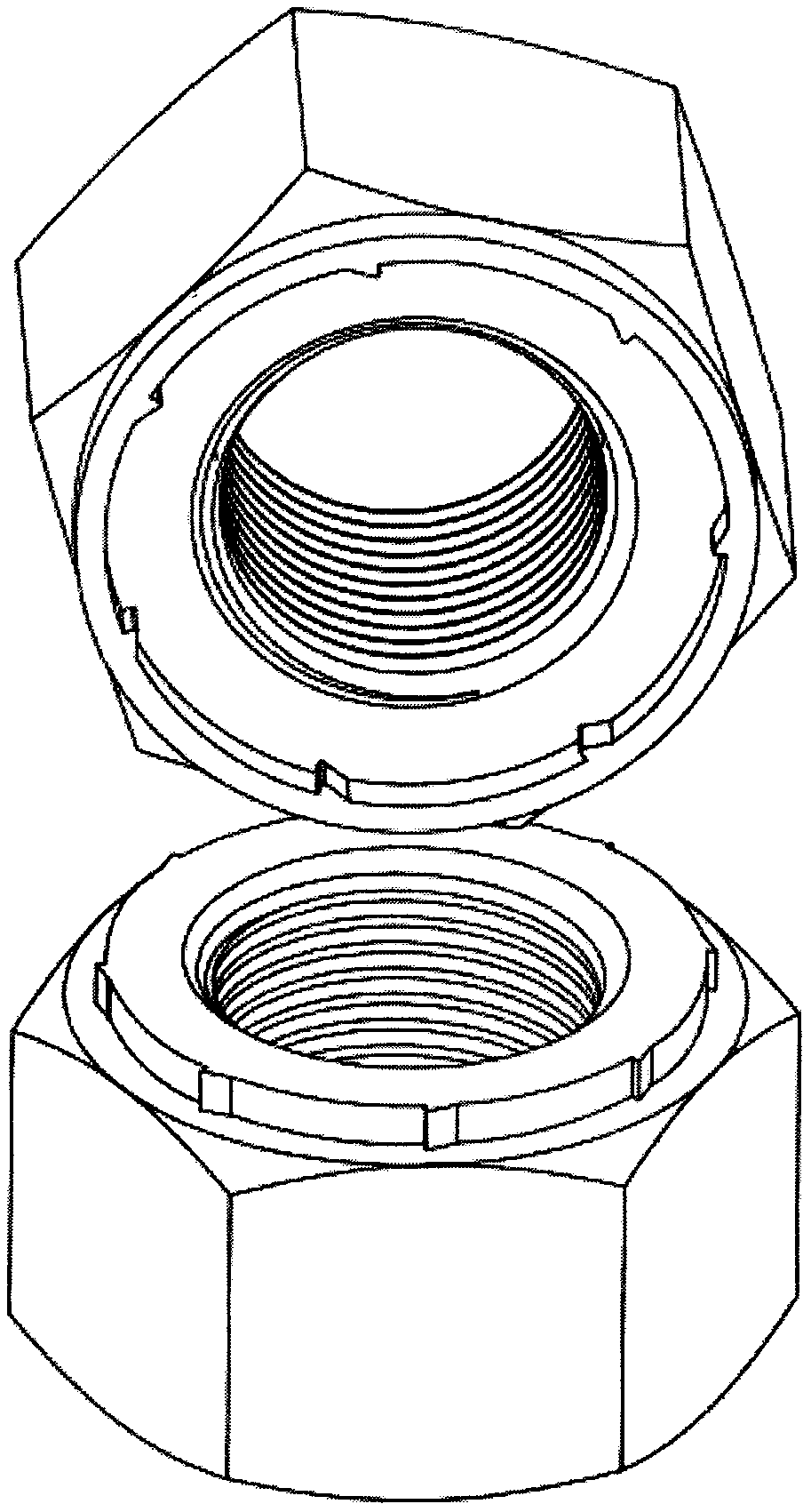
[0016] Such as figure 2 Shown, the ratchet of upper and lower nuts is located on the circumferential surface of the nut, and all the other are the same as embodiment 1. In this embodiment, the ratchet teeth are arranged on the circumferential surface of the nut, and the ratchet teeth are not affected by the huge extrusion force between the two nuts. During installation, the radial elastic deformation of the nuts is used to realize the ratchet teeth crossing and meshing with each other, which overcomes the problem of implementation. The disadvantage of the ratchet in Example 1 is that it is easily crushed and damaged during installation. The disadvantage is that the manufacturing difficulty is greater than that of Example 1.

Embodiment 3

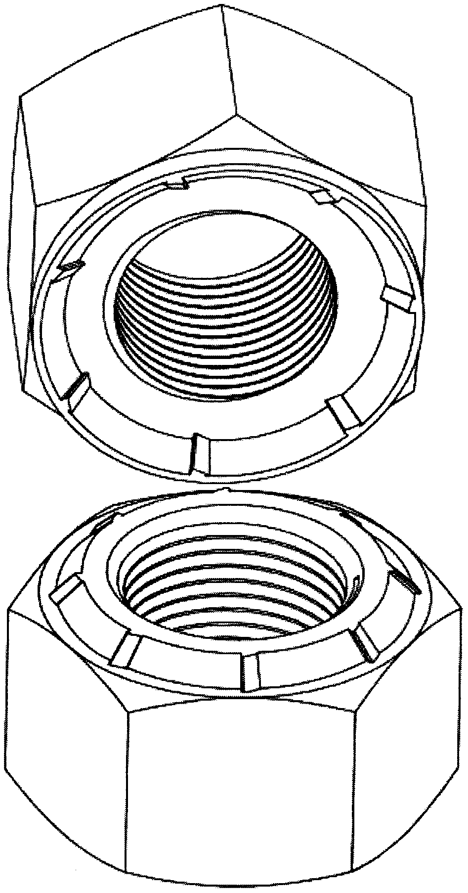
[0018] Such as image 3 As shown, the ratchets of the upper and lower nuts are located on the conical surface of the nut, and all the other are the same as in embodiment 1. In this embodiment, the ratchet teeth are arranged on the conical surface of the nut, and the nut can be elastically deformed in both the radial direction and the axial direction during installation to realize the ratchet teeth crossing and meshing with each other, taking into account the advantages and disadvantages of the first and second embodiments.


PUM


Abstract

The invention discloses a differential ratchet type anti-loosening double nut composed of an upper nut body and a lower nut body. The upper nut body and the lower nut body are provided with ratchets,and the ratchets of the upper nut body and the ratchets of the lower nut body are different in tooth number. A set of ratchets are engaged every time when the upper nut body and the lower nut body relatively rotate by a small angle, relative loosening between the double nut bodies is effectively prevented, and the defect that a traditional double nut achieves loosening preventing only through friction force is overcome.

Description

technical field [0001] The invention relates to a lock nut, in particular to an improved double nut. Background technique [0002] Nuts are widely used. In some vibration or important occasions, anti-loosening technology is required. Double nut anti-loosening is a widely used technology. However, in some more important or strong vibration occasions, ordinary double nuts still cannot achieve satisfactory results. Anti-loosening effect. There are many improved double nut technologies in the prior art, such as double nuts with eccentric sleeves and double nuts with tightening structure. The principle is basically to increase friction to prevent loosening. The relative rotation between the double nuts still cannot be prevented, and there are disadvantages such as complex structure, difficult processing, and high precision requirements for the matched screw rods. Contents of the invention [0003] The purpose of the present invention is to provide a differential ratchet type ...

Claims


Application Information

Patent Timeline
Patent Type & Authority Applications(China)
IPC IPC(8): F16B37/00F16B39/12
CPCF16B37/00F16B39/12
Inventor 杨天啸
Owner 杨天啸
Why Eureka
Try Eureka