Magneto-rheological fluid and electromagnetic friction combined transmission device driven by shape memory alloy

A magnetorheological fluid and memory alloy technology, applied in clutches, fluid clutches, mechanical equipment, etc., can solve the problems of magnetorheological fluids that cannot output torque, affect stable torque output, and affect the life of magnetorheological fluids. Achieve the effect of prolonging life, improving transmission and simple structure

Inactive Publication Date: 2020-07-28
CHONGQING UNIV OF TECH
View PDF3 Cites 0 Cited by
  • Summary
  • Abstract
  • Description
  • Claims
  • Application Information

AI Technical Summary

Problems solved by technology

[0005] 1. The magnetorheological fluid is always located in the working chamber. In this way, the magnetorheological fluid will be driven to flow during the rotation of the drive shaft, and the magnetic particles in the magnetorheological fluid will rub against each other, resulting in a decrease in the performance of the magnetorheological fluid and affecting Magnetorheological fluid life;
[0006] 2. When the temperature rises, the magnetorheological fluid cannot quickly and automatically output torque;
[0007] 3. When the temperature rises and the performance of the magnetorheological fluid decreases, the performance of the entire transmission device will also decrease. The existing transmission device cannot effectively compensate for the decrease in the performance of the magnetorheological fluid, thus affecting the stable output of torque

Method used


Image

  • Magneto-rheological fluid and electromagnetic friction combined transmission device driven by shape memory alloy
  • Magneto-rheological fluid and electromagnetic friction combined transmission device driven by shape memory alloy
  • Magneto-rheological fluid and electromagnetic friction combined transmission device driven by shape memory alloy

Examples


Embodiment

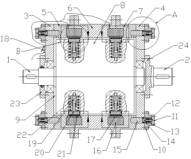
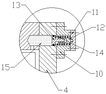
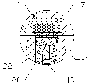
[0033] Example: see Figure 1 to Figure 3, a shape memory alloy driven magneto-rheological fluid and electromagnetic friction combined transmission device, including a driving shaft 1, a driven shaft 2 and a driven housing; the driven housing includes a left end cover 3, a right end cover 4 and a slave For the driving cylinder, the left end cover 3 and the right end cover 4 are respectively connected with the left and right ends of the driven cylinder. The driving shaft 1 passes through the left end cover 3 and extends into the driven housing, and is connected with the left end cover 3 and the right end cover 4 through bearings, and the driven shaft 2 is fixedly connected with the right end cover 4 . Wherein, the part of the driving shaft 1 located in the driven housing is expanded to form a transmission section 8, and a magneto-rheological fluid working chamber 9 is formed between the transmission section 8 and the driven housing. During specific implementation, a left beari...


PUM


Abstract

The invention discloses a combined transmission device with magnetorheological fluid driven by shape-memory alloy and electromagnetic friction. The device comprises a driving shaft, a driven shaft anda driven shell. A plurality of oil storage tanks are arranged around the whole circle of each of the two end faces of a driven cylinder. An oil fluid driving device is arranged outside a left end cover of the driven cylinder, and an oil fluid driving device is arranged outside a right end cover of the driven cylinder. An energizing coil is arranged at the position, close to each of the two ends,of the inner side of the driven cylinder. An outer friction ring is arranged on the inner side of each energizing coil. A plurality of containing grooves are formed in a transmission section. A guiderod is fixedly arranged in each containing groove. A guide groove is formed in the outer end of each guide rod. An armature push rod is further arranged in each containing groove. The outer end of each armature push rod is expanded to form a push section. An inner friction ring is fixed to the outer end of each push section. A second shape-memory alloy spring is arranged between each push sectionand the groove bottom of the corresponding containing groove. According to the combined transmission device with magnetorheological fluid driven by shape-memory alloy and electromagnetic friction, theservice life of magnetorheological fluid can be prolonged, the magnetorheological fluid is automatically controlled to carry out torque transmission, and the stability of torque transmission is guaranteed.

Description

technical field [0001] The invention relates to the technical field of transmission devices, in particular to a combined transmission device of magnetorheological fluid and electromagnetic friction driven by a shape memory alloy. Background technique [0002] Due to the good performance of magnetorheological fluid in transmission, such as flexible transmission between the main and driven parts, high sensitivity, high precision, and stable stepless speed regulation, it is easy to realize remote control and automatic control of the speed regulation process, etc. , so in recent years there have been more and more studies on the application of magnetorheological fluids in transmission, but the performance of magnetorheological fluids will decrease with the increase of ambient temperature (the performance will begin to decline when the temperature is higher than 80 ° C), which cannot meet the needs of transmission. The working requirements of the device in different temperature e...

Claims


Application Information

Patent Timeline
Patent Type & Authority Patents(China)
IPC IPC(8): F16D37/02
CPCF16D37/02
Inventor 黄金王西谢勇
Owner CHONGQING UNIV OF TECH
Why Eureka
Try Eureka