
Electrical connector

A technology of electrical connectors and circuit boards, which is applied in the direction of connection, fixed connection, circuit, etc., and can solve problems such as separation of welding parts, weak welding, and inclination of the insulating body

Active Publication Date: 2019-04-26
DEYI PRECISION ELECTRONIC IND CO LTD PANYU
View PDF4 Cites 0 Cited by
  • Summary
  • Abstract
  • Description
  • Claims
  • Application Information

AI Technical Summary

Problems solved by technology

[0003] However, in order to meet the requirement that the soldering portions of the plurality of terminals are flat against the circuit board to achieve good soldering, the soldering portions must have good flatness, so very precise assembly is required when installing the terminals. process, which increases the cost of the main assembly; moreover, during the soldering process of multiple terminals, the melting time of each solder is different, and the phenomenon that the insulating body is tilted during the soldering process also occurs, In severe cases, part of the welding part will leave the circuit board, affecting the welding effect, resulting in weak welding or even missing welding.

Method used


Image

  • Electrical connector
  • Electrical connector
  • Electrical connector

Examples


Embodiment Construction

[0027] In order to facilitate a better understanding of the purpose, structure, features, and effects of the present invention, the present invention will now be further described in conjunction with the accompanying drawings and specific embodiments.

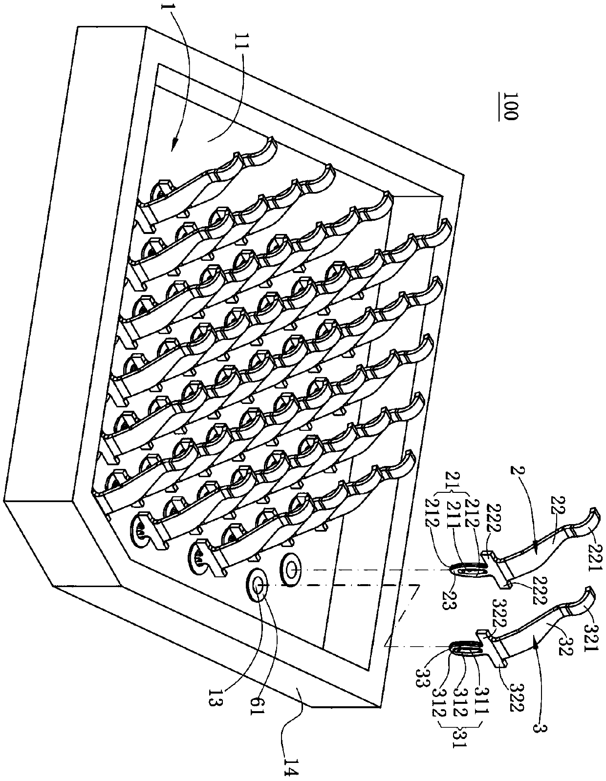
[0028] Such as figure 1 and Figure 6 As shown, the electrical connector 100 of the present invention is used to electrically connect a chip module 4 to a circuit board 5. The electrical connector 100 includes a body 1 and a plurality of terminals disposed on the body 1. The terminals are One end elastically contacts the chip module 4 , and the other end is welded to the circuit board 5 by a solder 7 .

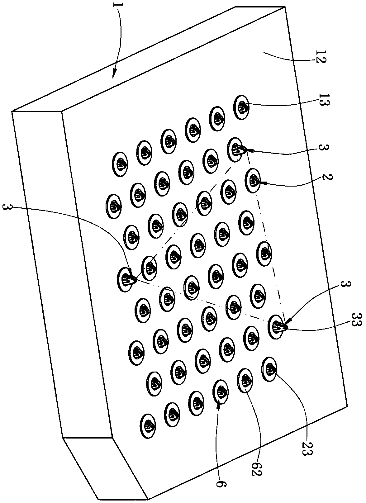
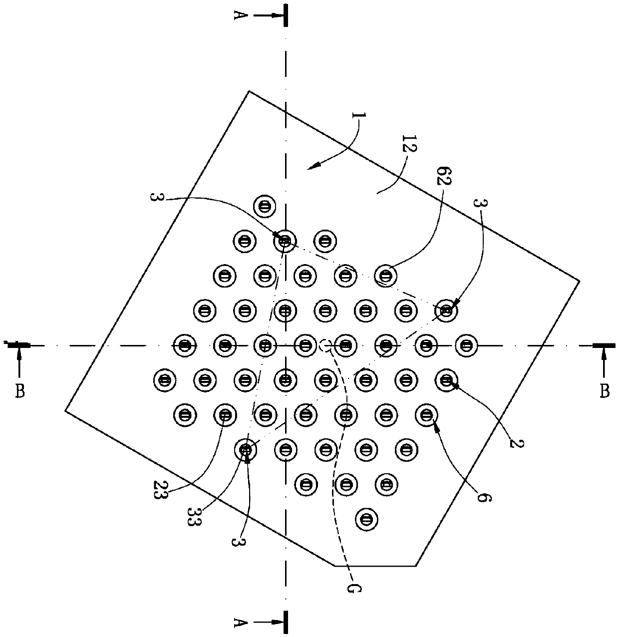
[0029] Such as figure 1 , figure 2 and image 3 As shown, the body 1 has a bearing surface 11 and a mounting surface 12, the body 1 is provided with a plurality of receiving holes 13 passing through the bearing surface 11 and the mounting surface 12, and a plurality of first terminals 2 The plurality of second terminals 3...


PUM


Abstract

The invention discloses an electrical connector comprising a body having a mounting surface; a plurality of first terminals are disposed on the body and arranged in at least three rows; at least threesecond terminals are disposed on the body, each of the second terminals is located in a different row and is offset from each other, and the second terminal has a guiding connection portion protruding from the mounting surface and used for abutting against a circuit board, and the guiding connection portion independently supports the body before being welded to the circuit board, so that the bodykeeps a certain distance from the circuit board. Compared with the prior art, at least three second terminals are respectively located in different rows and are mutually displaced, and the guiding connection portion independently supports the body before being welded to the circuit board, thereby avoiding tilting of the body during welding. The welding effect is ensured, to prevent the phenomenonthat welding is not firm or even solder skips occur.

Description

【Technical field】 [0001] The invention relates to an electrical connector, in particular to an electrical connector whose terminals are welded on a circuit board. 【Background technique】 [0002] An existing electrical connector comprises an insulating body and a plurality of terminals accommodated in the insulating body, a plurality of the terminals are arranged in multiple rows, and the terminals have a solder joint protruding from the insulating body. part, and the welding part is welded to a circuit board by a solder to realize electrical conduction. [0003] However, in order to meet the requirement that the soldering portions of the plurality of terminals are flat against the circuit board to achieve good soldering, the soldering portions must have good flatness, so very precise assembly is required when installing the terminals. process, which increases the main assembly cost; moreover, during the soldering process of multiple terminals, the melting time of each solde...

Claims


Application Information

Patent Timeline
Patent Type & Authority Applications(China)
IPC IPC(8): H01R12/57
CPCH01R12/57
Inventor 何建志
Owner DEYI PRECISION ELECTRONIC IND CO LTD PANYU
Learn More