Joints for Orthopedic Devices

A joint, articulated arm technology, applied in the joint field of orthopedic devices, can solve problems such as unpleasantness, click noise, interference, etc.

Active Publication Date: 2022-03-15
OTTOBOCK SE & CO KGAA
View PDF15 Cites 0 Cited by
  • Summary
  • Abstract
  • Description
  • Claims
  • Application Information

AI Technical Summary

Problems solved by technology

On the one hand, however, this has the disadvantage that the actual locking and locking of the pivoting movement in the first pivoting direction is only achieved at a certain angular position, ie when the teeth fit precisely into each other and intermesh.
On the other hand, there is a rattling or rattling noise due to the teeth sliding over each other, which is considered unpleasant and disturbing

Method used


Image

  • Joints for Orthopedic Devices
  • Joints for Orthopedic Devices
  • Joints for Orthopedic Devices

Examples


Embodiment Construction

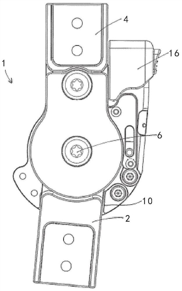
[0028] figure 1 A joint 1 according to a first embodiment of the invention is shown. The joint has a first joint arm 2 and a second joint arm 4 , which are mounted pivotably relative to one another about a pivot axis 6 . The pivot range over which this pivoting can occur is determined by the figure 1 A first stop not shown in the figure and a second stop 10 are delimited. exist figure 1 Inside the joint 1 shown in there is a locking element 12 and a contact surface 14, said locking element and contact surface in Figure 2 to Figure 5 shown in . Via the actuating element 16, the locking element 12 can change its position, whereby the locking device is brought from the locking position into the release position. To this end, in the illustrated embodiment, the operating element 16 is figure 1 must move up.

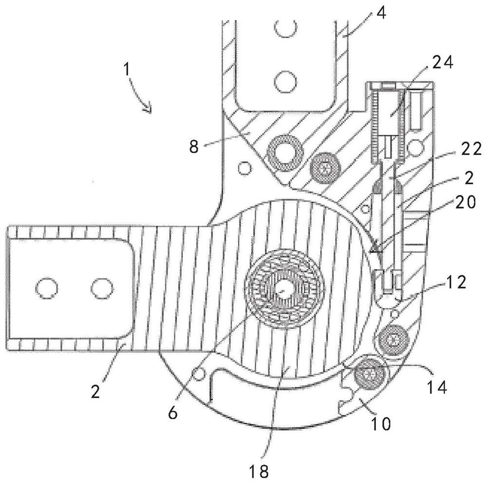
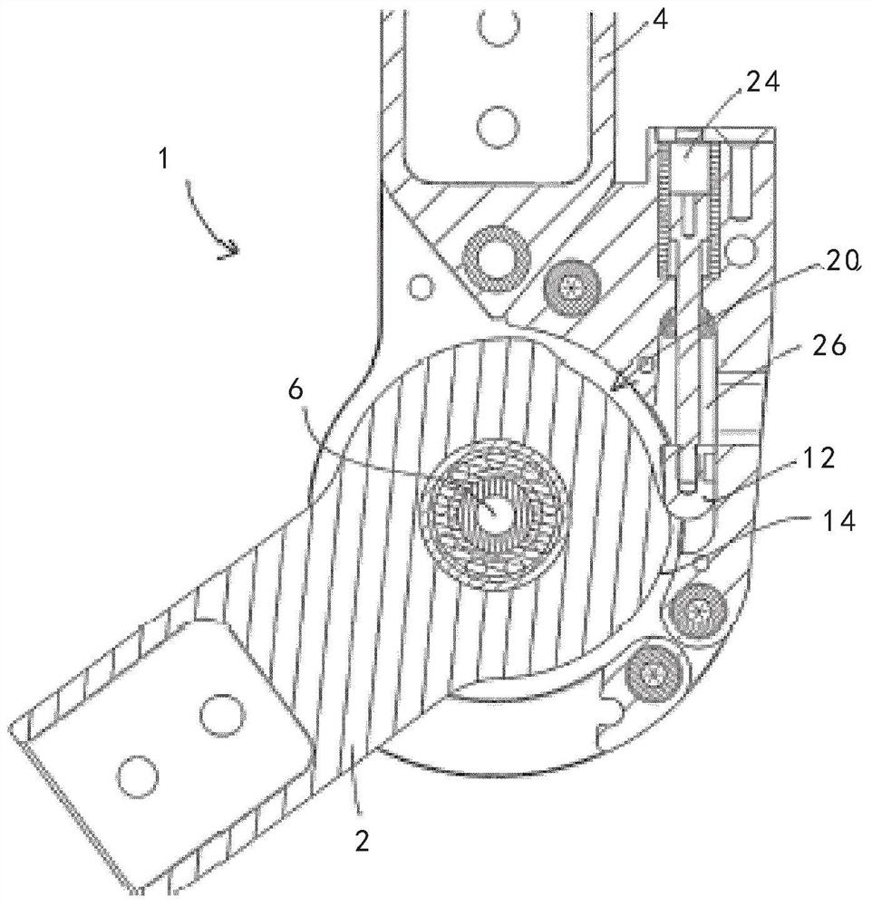
[0029] Figure 2 to Figure 5 show figure 1 Sectional view of joint 1 shown in . In the figure, compared to the figure, the first articulated arm 2 has been pivoted ...


PUM


Abstract

The invention relates to a joint (1) for an orthopedic device, said joint having a first articulated arm (2), a second articulated arm (4) and a locking device, said first and second articulated arms surrounding Pivot shafts (6) are pivotably supported relative to each other, the locking device can be brought into a release position and a locked position, wherein if the pivot angle between the first articulated arm and the second articulated arm Within a predetermined range, the locking device in the locked position locks the first articulated arm ( 2) Pivoting relative to said second articulated arm (4) in a first pivoting direction, and if the pivoting angle is outside said predetermined range, a locking device permits pivoting in said first pivoting direction of the pivot.

Description

technical field [0001] The invention relates to a joint for an orthopedic device, the joint having a first articulated arm, a second articulated arm and a locking device, the first articulated arm and the second articulated arm being pivotably mounted relative to one another about a pivot axis , the locking device can be brought into the released position and the locked position. Background technique [0002] Such joints are known, for example, from US 7,517,330 B2 and US 7,662,118 B2. They are used, for example, as joints for orthoses, such as knee orthoses, but can also be used for other orthoses or orthopedic devices. The first articulated arm and the second articulated arm are pivotably supported relative to each other about a pivot axis. Here, they pivot over a pivot range that is generally delimited by two stops, each of which is limited in one of two mutually opposite pivoting directions movement possibilities. When the locking device is in the released position, ...

Claims


Application Information

Patent Timeline
Patent Type & Authority Patents(China)
IPC IPC(8): A61F5/01
CPCA61F5/0125A61F2005/0158A61F2005/016A61F2005/0169A61F2005/0179A61F2005/0155A61F2005/0162
Inventor C·福格尔M·席林
Owner OTTOBOCK SE & CO KGAA
Why Eureka
Try Eureka