Frame lifting device for digital gallery

A lifting device and picture frame technology, applied in the direction of display tables, display hangers, display shelves, etc., can solve the problems of increasing the workload of staff, rationally adjusting their own positions, and many assembly and disassembly steps, so as to reduce assembly and disassembly steps, Reduce operational complexity and reduce the effect of structural components

Inactive Publication Date: 2019-04-30
兰州尖峰数码科技有限公司
View PDF0 Cites 0 Cited by
  • Summary
  • Abstract
  • Description
  • Claims
  • Application Information

AI Technical Summary

Problems solved by technology

[0002] As a fast and convenient way to display information on network media, it is being accepted by most people. As a specific implementation method of displaying information on network media, digital gallery can also introduce artist information while explaining in words. Visitors can even View enlarged images by clicking on thumbnails, etc., support the display of massive information, the number of placed works is unlimited, and the maintenance cost is low. It has been greatly developed and utilized in today's information society. However, most of the existing digital gallery frames use The fixed installation method, in the actual display process, cannot reasonably adjust its position according to different display requirements, the adaptability is poor, and the installation mechanism needs to be repeatedly assembled and disassembled, the operation is complicated, the assembly and disassembly steps are numerous, and the workload of the staff is increased

Method used


Image

  • Frame lifting device for digital gallery
  • Frame lifting device for digital gallery
  • Frame lifting device for digital gallery

Examples


Embodiment Construction

[0016] The following will clearly and completely describe the technical solutions in the embodiments of the present invention with reference to the accompanying drawings in the embodiments of the present invention. Obviously, the described embodiments are only some, not all, embodiments of the present invention. Based on the embodiments of the present invention, all other embodiments obtained by persons of ordinary skill in the art without making creative efforts belong to the protection scope of the present invention.

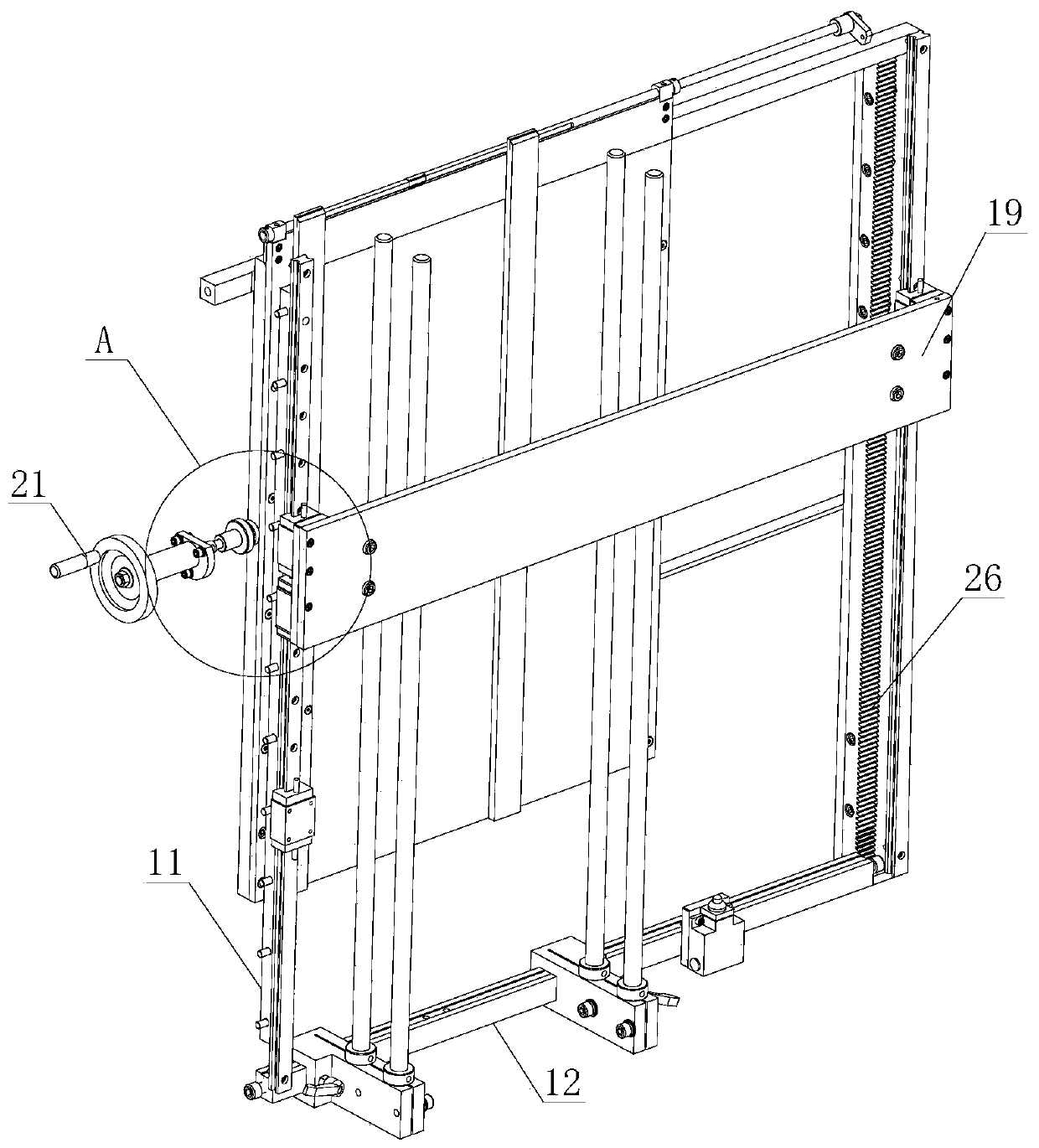
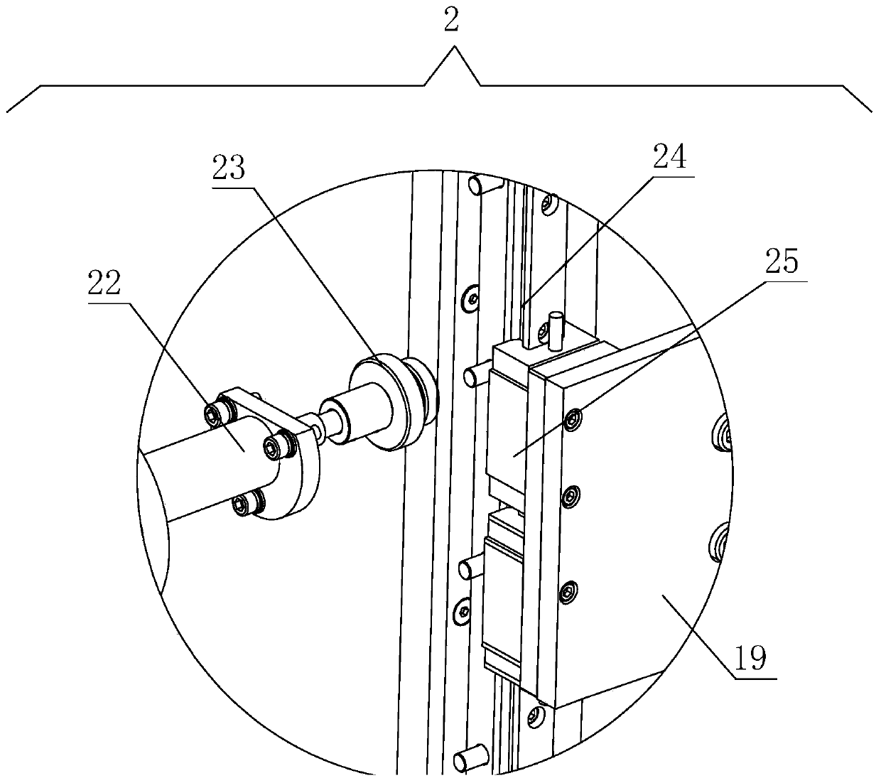
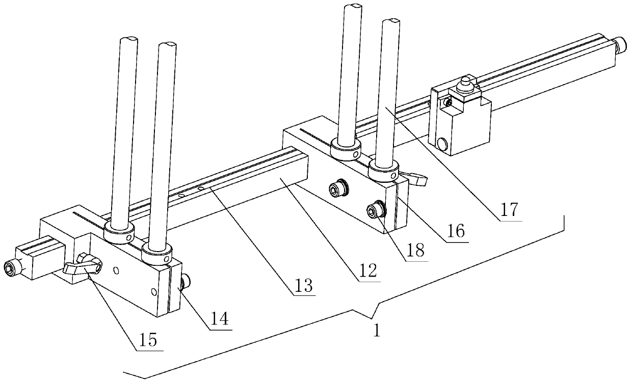
[0017] see Figure 1-3 , a digital gallery picture frame lifting device, including a mounting mechanism 1 and a lifting mechanism 2, the lifting mechanism 2 is located on the mounting mechanism 1, and the mounting mechanism 1 includes a mounting chassis 11, a chassis fixing beam 12, a lateral displacement groove 13, and a displacement block 14. Tightness adjustment rod 15, longitudinal displacement groove 16, limit shaft 17, fastening bolt 18 and limit plate 1...


PUM


Abstract

The invention discloses a frame lifting device for a digital gallery. The frame lifting device comprises a mounting mechanism and a lifting mechanism, wherein a mounting underframe is fixed on a wallboard, an electronic frame is placed between two limit shafts which limit the position of the electronic frame, the bottom of the electronic frame is supported by a limit plate, the limit plate limitsthe position of the electronic frame when playing a supporting role, so that structural components are reduced, and mounting is convenient; a handle is rotated to enable a hinge wheel to drive radialsliders to move vertically in the areas of radial chutes, and radial adjustment of the electronic frame is realized; displacement blocks move left and right in a transverse displacement groove, and the horizontal position of the electronic frame is adjusted; compared with the traditional fixed electronic frame, the demand for different show heights is met, the practicability is improved, the complicated operation caused by repeated mounting and dismounting of a mounting mechanism is reduced, mounting and dismounting steps are reduced, and workload of a worker is reduced.

Description

technical field [0001] The invention relates to the technical field of digital galleries, in particular to a digital gallery picture frame lifting device. Background technique [0002] As a fast and convenient way to display information on network media, it is being accepted by most people. As a specific implementation method of displaying information on network media, digital gallery can also introduce artist information while explaining in words. Visitors can even View enlarged images by clicking on thumbnails, etc., support the display of massive information, the number of placed works is unlimited, and the maintenance cost is low. It has been greatly developed and utilized in today's information society. However, most of the existing digital gallery frames use The fixed installation method, in the actual display process, cannot reasonably adjust its position according to different display requirements, the adaptability is poor, and the installation mechanism needs to be ...

Claims


Application Information

Patent Timeline
Patent Type & Authority Applications(China)
IPC IPC(8): A47F3/00A47F5/08A47F7/14F16M11/04F16M11/18F16M13/02
CPCA47F3/004A47F5/0838A47F7/144F16M11/045F16M11/046F16M11/18F16M13/02
Inventor 张万斌
Owner 兰州尖峰数码科技有限公司
Why Eureka
Try Eureka