Clamp-type patella anchor guider

A clamping and guide technology, which is applied in the direction of bone drill guidance, etc., can solve the problems of affecting the fixation operation, low accuracy, and hole deviation, etc., and achieves the effect of convenient operation, high positioning accuracy, and avoiding wounds

Pending Publication Date: 2019-05-03
上海节惠生物科技有限公司
View PDF0 Cites 2 Cited by
  • Summary
  • Abstract
  • Description
  • Claims
  • Application Information

AI Technical Summary

Problems solved by technology

[0003] In the traditional method, the surgeon usually drills a hole from the middle of the lateral patella based on experience. Although this method has a certain effect, the accuracy of this method is low, and it is easy to make the hole off the top or bottom of the patella, which affects the follow-up. Fixed operation, which brings inconvenience to the operation of patients

Method used


Image

  • Clamp-type patella anchor guider
  • Clamp-type patella anchor guider
  • Clamp-type patella anchor guider

Examples


Embodiment 1

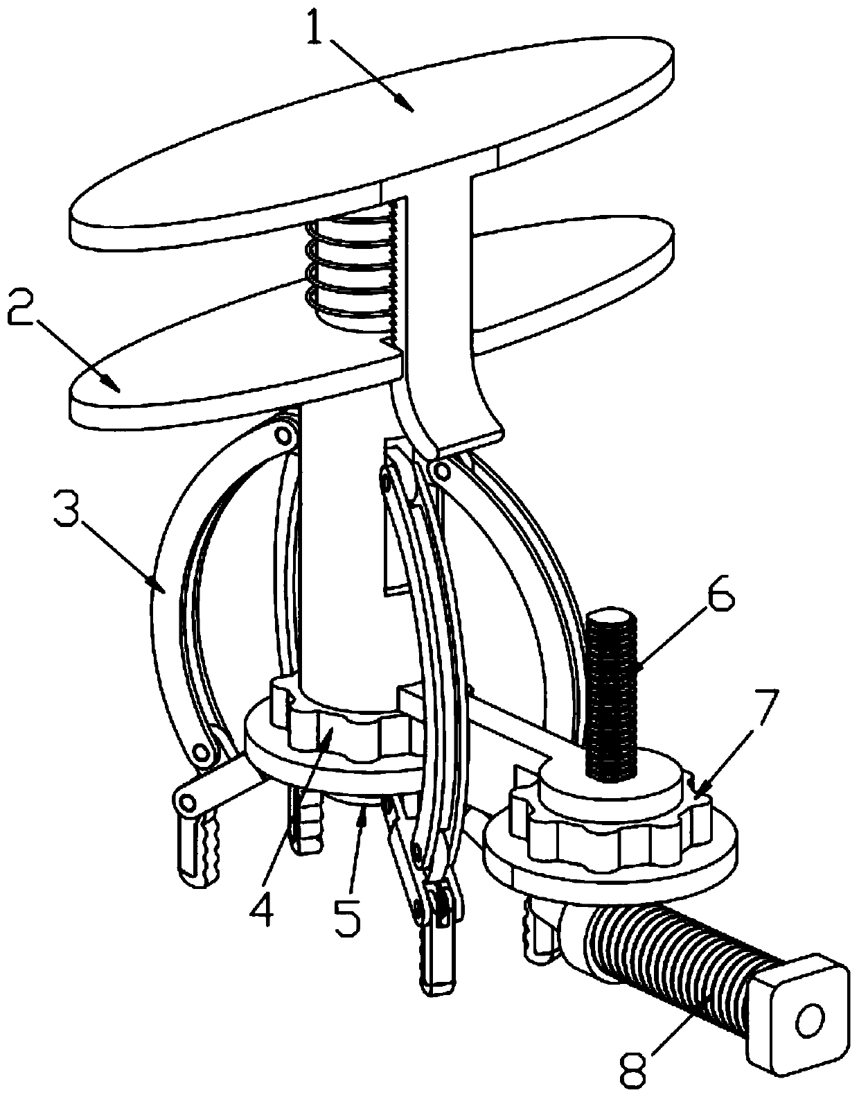
[0044] A clip-type patella anchor guide, including a push rod 1, a main body 2, a movable part 3, a top plate 5, an adjustment screw 6 and a guide tube 8, the push rod 1 is installed on the upper part of the main body 2, and the movable part 3 is hinged on the main body 2 The lower part and a plurality of movable parts 3 evenly surround the main body 2, the top plate 5 is installed on the bottom of the main body 2 and the first fine-tuning knob 4 is screwed between the top plate 5 and the main body 2, and the adjustment screw 6 and the guide tube 8 are connected with each other. The main body 2 is hinged, and a second fine-tuning knob 7 is screwed under the adjusting screw 6 .

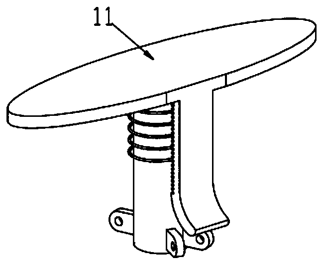
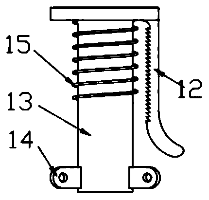
[0045]One side of the push rod adopts a T-shaped structure. The push rod includes a first operating panel 11, a limit shrapnel 12, a rod body 13 and a push rod connecting end 14. , there is a certain angle between the two push rod connecting ends 14 on the same side; the rod body 13 is a hollow ring, a...

Embodiment 2

[0050] A clip-type patella anchor guide, including a push rod 1, a main body 2, a movable part 3, a top plate 5, an adjustment screw 6 and a guide tube 8, the push rod 1 is installed on the upper part of the main body 2, and the movable part 3 is hinged on the main body 2 The lower part and a plurality of movable parts 3 evenly surround the main body 2, the top plate 5 is installed on the bottom of the main body 2 and the first fine-tuning knob 4 is screwed between the top plate 5 and the main body 2, and the adjustment screw 6 and the guide tube 8 are connected with each other. The main body 2 is hinged, and a second fine-tuning knob 7 is screwed under the adjusting screw 6 .

[0051] The top plate 5 includes a top plate rod body provided with a first external thread 51 and a top board base 52 positioned at the bottom of the top board rod body. The top board base 52 is fixedly connected with a second elastic pad 53, the connection mode is similar to that of the first elastic p...


PUM


Abstract

The invention discloses a clamp-type patella anchor guider, relates to the field of medical instruments, and solves the shortcomings of drilling from the middle of the lateral position of patella according to experience. The product comprises a push rod, a main body, a movable part, a top plate, an adjustment screw and a guiding tube, the push rod is installed on the upper part of the main body, the movable part is hinged to the lower part of the main body, the top plate is installed at the bottom end of the main body and a fine adjustment knob is arranged between the top plate and the main body in a screwing mode, both the adjustment screw and the guiding tube are hinged to the main body, and the lower part of the adjustment screw is in screwing connection with a second fine adjustment knob. The product provides a better fixing effect by a first elastic pad on a clamping jaw and the top plate, and ensures that the relative position of the guider and the patella is unchanged after being fixed; the product ensures the accuracy of the drilling position through the fine adjustment of the components on one side of the guiding tube; and the product is simple in structure, convenient tooperate and high in positioning precision, effectively improves the operation efficiency in the operation, and improves the fixation effect of the patella anchor.

Description

technical field [0001] The invention relates to the field of medical instruments, in particular to a clamping type patella anchor guider. Background technique [0002] With the advancement of medical technology, at present, operations such as patella fixation and repair are mostly carried out using minimally invasive methods. Minimally invasive methods refer to the methods of diagnosis and treatment of spinal diseases through non-traditional surgical methods with the help of special surgical instruments, instruments or other means. It is a technology that only causes minimal trauma to the patient during the treatment process and leaves only minimal wounds after the operation. Wherein, when the lateral position of the patella is fixed, pre-drilled holes are required to facilitate the fixation of the anchor. [0003] In the traditional method, the surgeon usually drills a hole from the middle of the lateral patella based on experience. Although this method has a certain effec...

Claims


Application Information

Patent Timeline
Patent Type & Authority Applications(China)
IPC IPC(8): A61B17/17
Inventor 张正伟常艳星张俊星
Owner 上海节惠生物科技有限公司
Why Eureka
Try Eureka