Novel electronic component resistor sleeve penetrating equipment

A technology for electronic components and bushings, applied in electrical components, resistors, resistor components, etc., can solve the problems of no longer protecting thermal resistance, vibration, etc., to avoid relative position changes and increase friction. Effect

Active Publication Date: 2022-07-26
南通迈威智能科技有限公司
View PDF6 Cites 0 Cited by
  • Summary
  • Abstract
  • Description
  • Claims
  • Application Information

AI Technical Summary

Problems solved by technology

[0003] At present, thermal resistors need to be installed in the internal circuit of electronic components to monitor the temperature of the circuit, and an insulating sleeve needs to be installed to protect the thermal resistor. After the existing sleeve is sleeved on the side of the thermal resistor, due to the sleeve and There is a certain friction force in the thermal resistance, so that the bushing will not slide on the surface of the thermal resistance. However, after a long time of use, due to the difference in the heat dissipation of the thermal resistance, that is, the current flowing through the thermal resistance is different, or the electronic components stop working and heat up. Resistance cooling makes the inner wall of the casing alternate between cold and hot, and then plasticizes, so the friction between the casing and the thermal resistor will be reduced, and electronic components installed in different devices will inevitably vibrate, so after plasticization The bushing may move relative to the thermal resistor and no longer protect the thermal resistor

Method used


Image

  • Novel electronic component resistor sleeve penetrating equipment
  • Novel electronic component resistor sleeve penetrating equipment
  • Novel electronic component resistor sleeve penetrating equipment

Examples


Embodiment 1

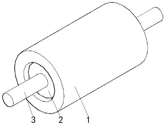
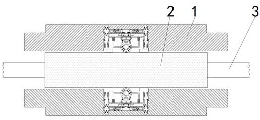
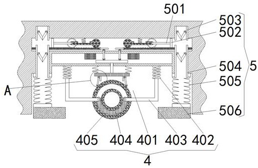
[0023] see Figure 1-Figure 5 , a new type of electronic component resistance through casing equipment, including a casing 1, the interior of the casing 1 is provided with a thermal resistance 2, the two sides of the thermal resistance 2 are fixedly connected with connecting wires 3, and the interior of the casing 1 includes a positioning mechanism 4, The positioning mechanism 4 includes a detection cavity 401 opened on the inner wall of the housing 1, and a contraction spring 402 is fixedly connected to the inner wall of the detection cavity 401 away from the thermal resistance 2 side. The contraction spring 402 is initially in a state of being squeezed and contracted, so that the squeeze wheel 405 continues to squeeze the thermal resistance 2, the side of the contraction spring 402 close to the thermal resistance 2 is fixedly connected with the support frame 403, the other side of the support frame 403 is rotatably connected with the support arc block 404, and the side of the...

Embodiment 2

[0028] see Figure 1-Figure 5 , a new type of electronic component resistance through casing equipment, including a casing 1, the interior of the casing 1 is provided with a thermal resistance 2, the two sides of the thermal resistance 2 are fixedly connected with connecting wires 3, and the interior of the casing 1 includes a positioning mechanism 4, The inside of the housing 1 includes a tightening mechanism 5, and the tightening mechanism 5 includes an inflatable rod 501 rotatably connected to the side of the driving wheel 416, and an inflatable plate 502 is fixedly connected to the side of the inflatable rod 501 away from the center of the air cavity 418, and the air cavity 418 is far away from the center. One side of the thermal resistance 2 is interspersed with a one-way air intake pipe 503, and the other side of the air cavity 418 is interspersed with an inflatable pipe 504. The inflatable pipe 504 communicates with the air spring 505 and the air cavity 418 respectively, a...

Embodiment 3

[0031] see Figure 1-Figure 5 , a new type of electronic component resistance through casing equipment, including a casing 1, the interior of the casing 1 is provided with a thermal resistance 2, the two sides of the thermal resistance 2 are fixedly connected with connecting wires 3, and the interior of the casing 1 includes a positioning mechanism 4, The positioning mechanism 4 includes a detection cavity 401 opened on the inner wall of the housing 1, and a contraction spring 402 is fixedly connected to the inner wall of the detection cavity 401 away from the thermal resistance 2 side. The contraction spring 402 is initially in a state of being squeezed and contracted, so that the squeeze wheel 405 continues to squeeze the thermal resistance 2, the side of the contraction spring 402 close to the thermal resistance 2 is fixedly connected with the support frame 403, the other side of the support frame 403 is rotatably connected with the support arc block 404, and the side of the...


PUM


Abstract

The invention provides novel electronic component resistor sleeve penetrating equipment which comprises a shell, a thermal resistor is arranged in the shell, connecting wires are fixedly connected to the two sides of the thermal resistor, a positioning mechanism is arranged in the shell, and a tightening mechanism is arranged in the shell. According to the novel electronic component resistor sleeve penetrating equipment, during use, the sleeve shell is inserted into the side face of a thermal resistor to protect the thermal resistor, when the inner wall of the shell is plasticized, the extrusion force between the inner wall of the shell and the side face of the thermal resistor is reduced, the friction force between the inner wall of the shell and the side face of the thermal resistor is reduced, and under the action of vibration, when the shell moves relative to the thermal resistor, the thermal resistor is protected. When the casing is plasticized and moves relative to the thermal resistor, the positioning mechanism restores the movement of the casing through the extrusion wheel to ensure that the relative position between the casing and the thermal resistor is unchanged, so that the effect that the thermal resistor cannot be continuously protected due to the change of the relative position between the casing and the thermal resistor when the casing is plasticized and moves relative to the thermal resistor is achieved.

Description

technical field [0001] The invention relates to the technical field of thermistors, in particular to a novel electronic component resistance bushing device. Background technique [0002] Thermistor, also known as thermal resistance, is a kind of resistor, and it is also the most commonly used temperature detector in the medium and low temperature area. It is based on the characteristic that the resistance value of the metal conductor increases with the increase of temperature. , its main features are high measurement accuracy and stable performance, among which the measurement accuracy of platinum thermal resistance is the highest. It is not only widely used in industrial temperature measurement, but also made into a standard benchmark. [0003] At present, a thermal resistance needs to be installed in the internal circuit of electronic components to monitor the temperature of the circuit, and an insulating sleeve needs to be set to protect the thermal resistance. The therm...

Claims


Application Information

Patent Timeline
Patent Type & Authority Applications(China)
IPC IPC(8): H01C1/022H01C7/00
CPCH01C1/022H01C7/008
Inventor 胡伟忠
Owner 南通迈威智能科技有限公司
Why Eureka
Try Eureka