A positioning and clamping device for machining

A technology of positioning clamping and mechanical processing, which is applied in the direction of positioning devices, metal processing equipment, metal processing machinery parts, etc., can solve the problems of poor positioning clamping effect and affecting processing quality, etc., and achieves convenient installation, complete functions and reasonable structure simple effect

Active Publication Date: 2020-05-08
太仓市富远精密模具有限公司
View PDF5 Cites 0 Cited by
  • Summary
  • Abstract
  • Description
  • Claims
  • Application Information

AI Technical Summary

Problems solved by technology

[0003] The object of the present invention is to provide a positioning and clamping device for mechanical processing in order to solve the above problems, which solves the problem that the existing positioning and clamping devices for mechanical processing have relatively poor positioning and clamping effects, which seriously affects the processing quality. question

Method used


Image

  • A positioning and clamping device for machining
  • A positioning and clamping device for machining
  • A positioning and clamping device for machining

Examples


Embodiment Construction

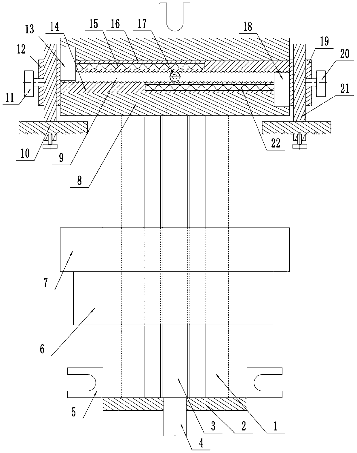
[0018] Such as figure 1 As shown, this specific embodiment adopts the following technical solutions: a positioning and clamping device for machining, including a guide rail seat 1, an end cover 2, a screw rod 3, a connector 4, a locking seat 5, a nut seat 6, a movable Clamping seat 7, fixed clamping seat 8, through groove 9, positioning assembly-10, locking screw-11, connecting block-12, fixed cover-13, rack body-14, tension spring-15, rack body Two 16, connecting gear 17, fixed cover two 18, connecting block two 19, locking screw two 20, positioning assembly two 21 and tension spring two 22; said guide rail seat 1 is movably connected with nut seat 6, said guide rail seat 1 The rear side is fixedly connected with a fixed clamping seat 8; the longitudinal threaded hole on the lower side of the nut seat 6 is movably connected with the screw rod 3, and the rear side of the nut seat 6 is fixedly connected with a movable clamping seat 7; the screw rod 3 The end cover 2 is movably...


PUM


Abstract

The invention discloses a positioning and clamping device for machining. The device comprises a guide rail base, an end cover, a screw rod, a connecting head, a locking base, a nut base, a movable clamping base, a fixed clamping base, a through groove, a first positioning module, a first locking screw, a first rack body, a first tension spring, a second rack body, a connecting gear, a second fixedcover, a second connecting block, a second locking screw, a second positioning module and a second tension spring. The device is reasonable and simple in structure; the connecting gear is provided toguarantee synchronous movement of the first rack body and the second rack body to the outer side or the inner side, so that the centers of workpieces can be positioned in the center position betweenthe movable clamping base and the fixed clamping base, and are always positioned in a fixed position for machining to improve the machining quality; the connecting head is driven to rotate through a spanner; and through rotation of the connecting head, the screw rod is rotated to drive the nut base to drive the movable clamping base to directly clamp the workpieces, so that the positioning and clamping efficiency is improved.

Description

technical field [0001] The invention relates to the technical field of machining equipment, in particular to a positioning and clamping device for machining. Background technique [0002] Machining refers to the process of changing the external dimension or performance of a workpiece through a mechanical device, and the positioning clamping device is used to fix the processing object in the process of mechanical manufacturing so that it occupies the correct position for construction or testing. When the device and mechanical parts are processed, if the parts are not installed tightly, it will cause inconvenience to the processing and affect the processing accuracy; while the positioning and clamping effect of the existing positioning clamping device for machining is relatively poor, which seriously affects the quality of processing . Contents of the invention [0003] The object of the present invention is to provide a positioning and clamping device for mechanical proces...

Claims


Application Information

Patent Timeline
Patent Type & Authority Patents(China)
IPC IPC(8): B23Q3/00
Inventor 周松茂
Owner 太仓市富远精密模具有限公司
Why Eureka
Try Eureka