
Adjustable positioning and clamping device for regular polygonal dynamic sculpture and adjustable positioning method thereof

A regular polygon, dynamic sculpture technology, applied in decorative art, pivot connection, decorative structure, etc., can solve the problems of difficult manufacturing, inability to ensure uniform and stable rotation of dynamic sculpture, and extremely high manufacturing precision requirements.

Active Publication Date: 2019-05-03
JIMEI UNIV
View PDF12 Cites 0 Cited by
  • Summary
  • Abstract
  • Description
  • Claims
  • Application Information

AI Technical Summary

Problems solved by technology

At present, the common dynamic sculptures on the market mostly adopt the structure of integral collar, such as the utility model prior patent with the application number 201220057572.X, which discloses a three-axis six-ring space three-dimensional cross dynamic sculpture. The prior utility model patent No. 201120010148.5 discloses a space-rotating dynamic sculpture with multiple collars. The dynamic sculpture disclosed in the above-mentioned prior patent has the problems of high manufacturing difficulty, high cost, and inconvenient installation, disassembly and maintenance.
The dynamic sculpture involved in the US patent application US29138745 is driven by wind, and also adopts an integral structure, which requires extremely high overall manufacturing precision of the dynamic sculpture, and cannot guarantee the uniform and stable rotation of the dynamic sculpture
The elbow connector involved in the prior Chinese utility model patent with application number 201720116727.5 can be used to connect the adjacent axis of regular polygon dynamic sculpture, but this method cannot change the connection angle according to the angle of any adjacent side of regular polygon

Method used


Image

  • Adjustable positioning and clamping device for regular polygonal dynamic sculpture and adjustable positioning method thereof
  • Adjustable positioning and clamping device for regular polygonal dynamic sculpture and adjustable positioning method thereof
  • Adjustable positioning and clamping device for regular polygonal dynamic sculpture and adjustable positioning method thereof

Examples


Embodiment Construction

[0020] In order to further explain the technical solution of the present invention, the present invention will be described in detail below through specific examples.

[0021] In describing the present invention, it should be understood that the terms "center", "longitudinal", "transverse", "upper", "lower", "front", "rear", "left", "right", " Vertical", "horizontal", "top", "bottom", "inner", "outer" and other indication orientations or positional relationships are based on the orientations or positional relationships shown in the drawings, and are only for the convenience of describing the present invention and simplifying Describes, but does not indicate or imply that the device or element referred to must have a specific orientation, be constructed in a specific orientation, and operate in a specific orientation, and therefore should not be construed as limiting the invention. In the description of the present invention, unless otherwise specified, "plurality" means two or...


PUM


Abstract

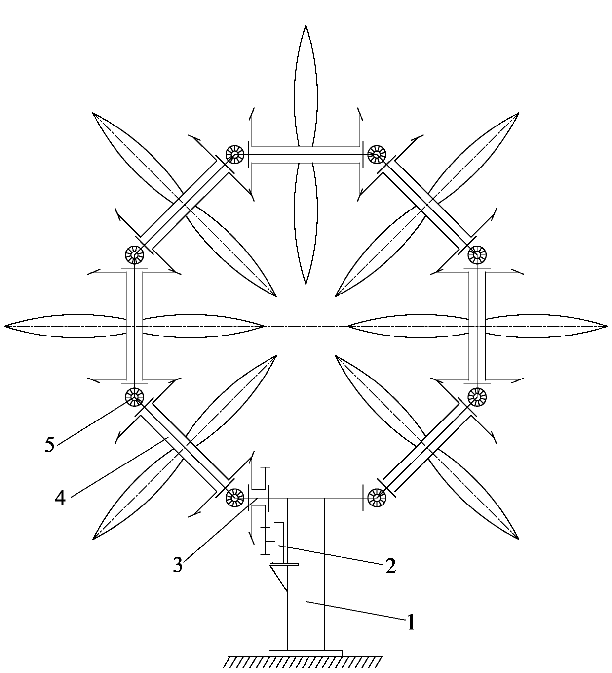
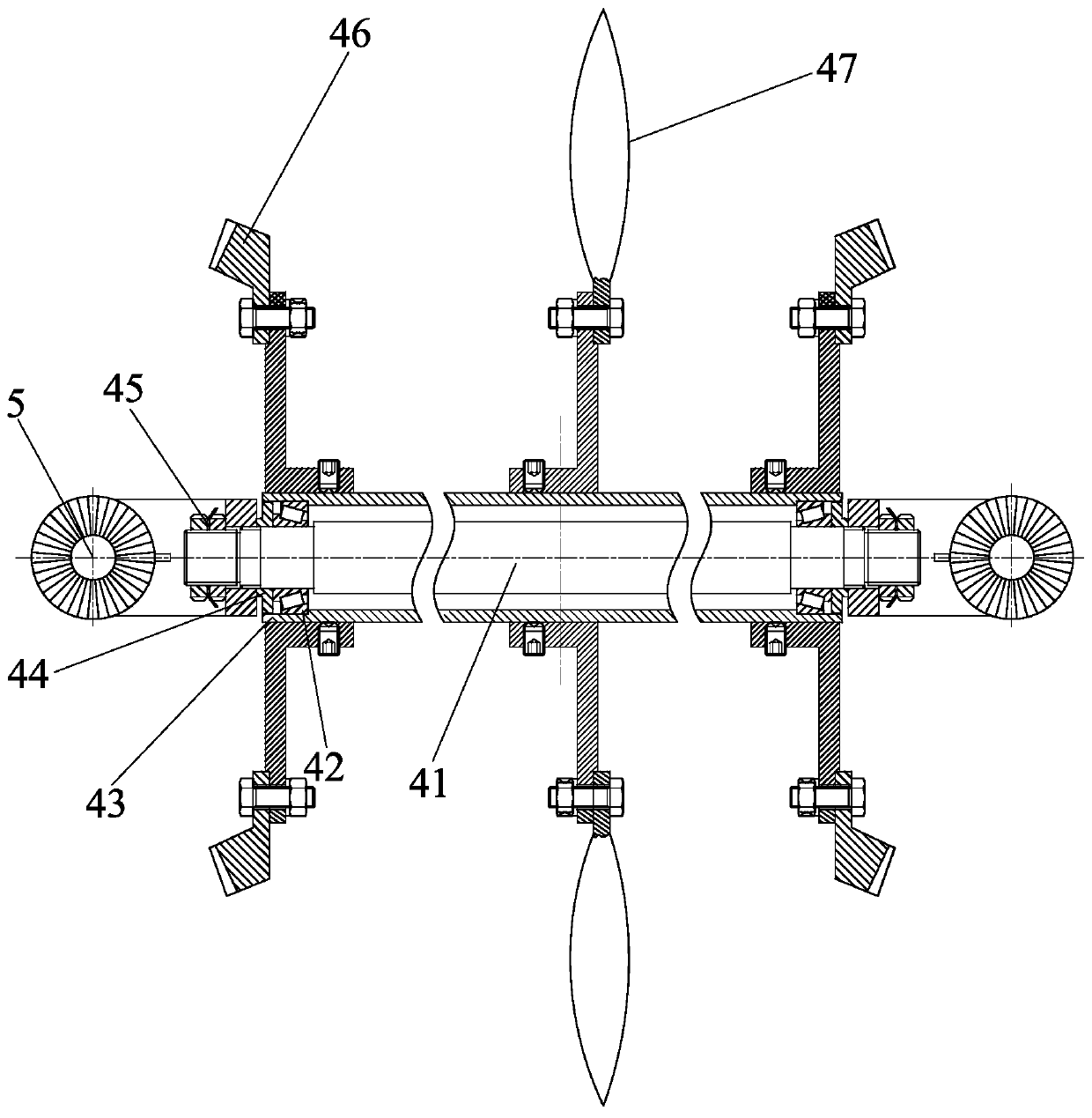
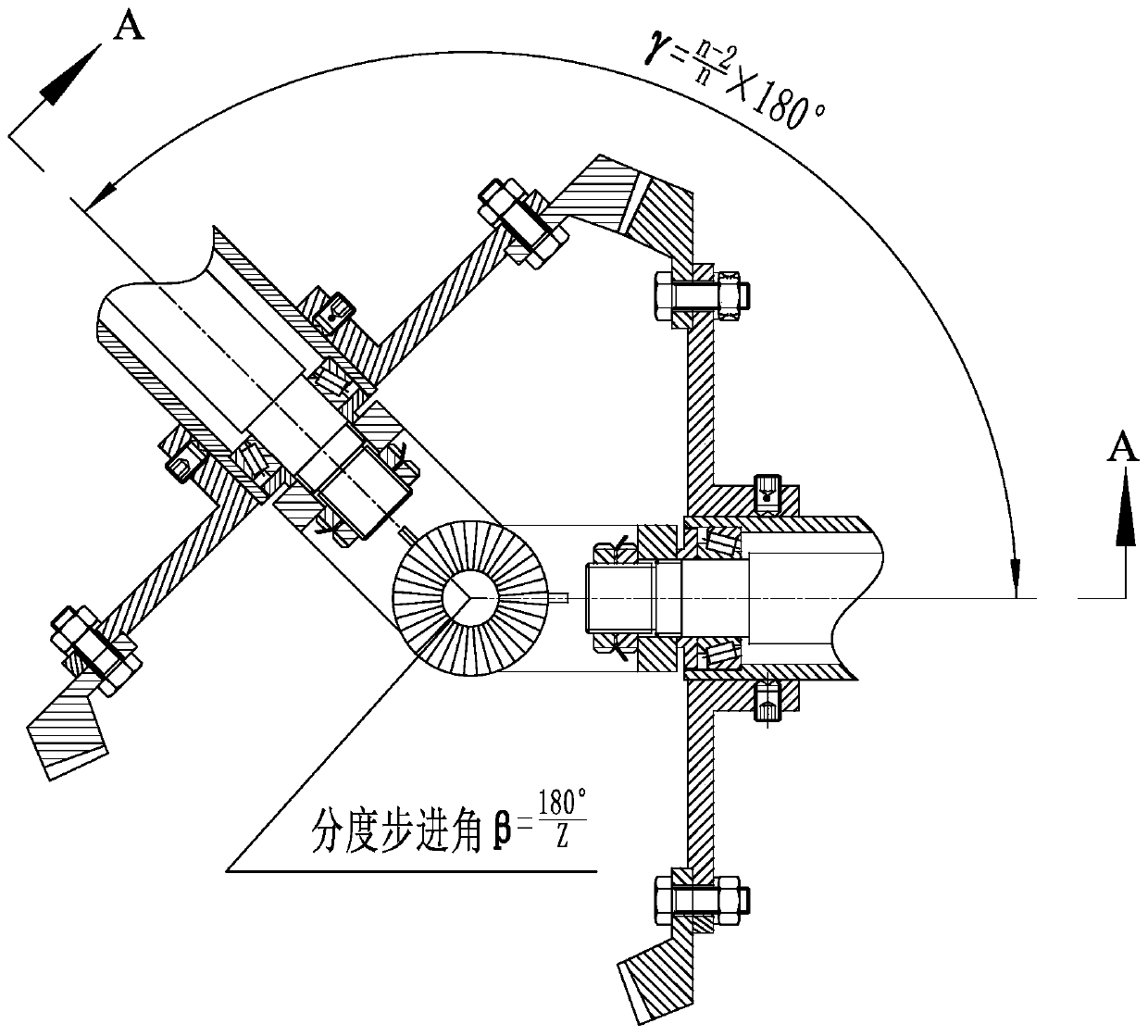
The invention discloses an adjustable positioning and clamping device for a regular polygonal dynamic sculpture and an adjustable positioning method thereof. The regular polygonal dynamic sculpture comprises a stand column, a driving mechanism, a transverse support beam module, a rotating sculpture module and an adjustable positioning and clamping module; and the adjustable positioning and clamping module comprises two adjustable positioning discs, two L-shaped connecting blocks and high-strength thread connecting pieces. The dynamic sculpture is assembled by modular modules, is driven by adopting a speed reducing motor, is simple and reasonable in structure, is free of influencing overall beauty, can guarantee uniform and stable rotation, and has the advantages of high adjusting precision, simple structure, reliable connection, high positioning precision, capability of quickly mounting and dismounting and few fitting types.

Description

technical field [0001] The invention relates to the technical field of sculpture landscape devices, in particular to an adjustable positioning clamping device and an adjustable positioning method for regular polygon dynamic sculptures. Background technique [0002] Kinetic sculpture is a kind of plastic art, a combination of science and technology and art, and it is approaching our life. At present, the common dynamic sculptures on the market mostly adopt the structure of integral collar, such as the utility model prior patent with the application number 201220057572.X, which discloses a three-axis six-ring space three-dimensional cross dynamic sculpture. The prior utility model patent No. 201120010148.5 discloses a space rotating dynamic sculpture with multiple collars. The dynamic sculpture disclosed in the above prior patent has the problems of high manufacturing difficulty, high cost, and inconvenient installation, disassembly and maintenance. The dynamic sculpture invo...

Claims


Application Information

Patent Timeline
IPC IPC(8): B44C3/06B44C3/12F16C11/04
CPCY02E10/50
Inventor 许志龙李煌常跃中刘菊东皮钧杨小璠黄种明沈志煌姜涛
Owner JIMEI UNIV
Learn More