

Damping rigid-frame bridge pier having buckling restrained braces
A technology of buckling constraints and bridge piers, which is applied to bridges, bridge construction, bridge parts, etc., can solve problems such as improvement, and achieve the effect of improving earthquake resistance, protecting the main structure of the bridge, and reducing damage
- Summary
- Abstract
- Description
- Claims
- Application Information
AI Technical Summary
Problems solved by technology
Method used
Image

Examples
Embodiment 1
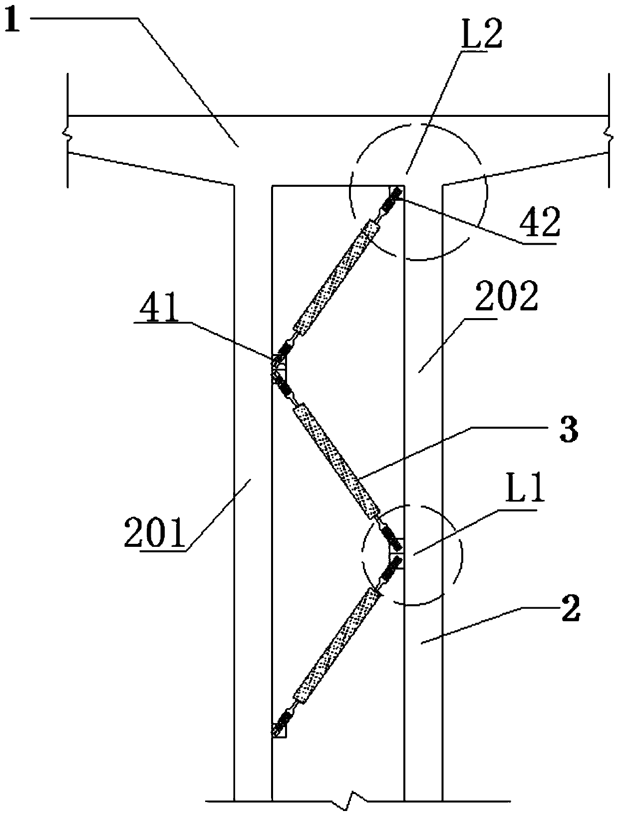
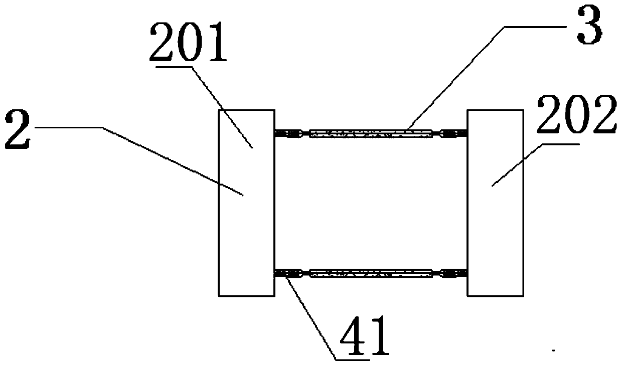
[0053] see figure 1 , a kind of shock-absorbing rigid frame bridge pier containing buckling restraint support, is characterized in that: comprise main girder 1 and double limb thin-walled pier 2, and some buckling restraint support 3 and embedded steel member 141.
[0054] The double-leg thin-walled pier 2 includes A limb 201 and B limb 202 perpendicular to the horizontal plane. Both the upper ends of the A limb 201 and the B limb 202 are connected under the main beam 1 .
[0055] When pouring the double-leg thin-walled pier 2, several pre-embedded steel components I41 are pre-embedded inside the A-leg 201 and the B-leg 202. The part of each pre-embedded steel member I41 exposed to the concrete surface is a connecting steel plate I411.
[0056] Each of the connecting steel plates I411 on the A limb 201 is located on the surface facing the B limb 202 . Each of the connecting steel plates I411 on the B limb 201 is located on the surface facing the A limb 202 .
[0057]Disloc...
Embodiment 2
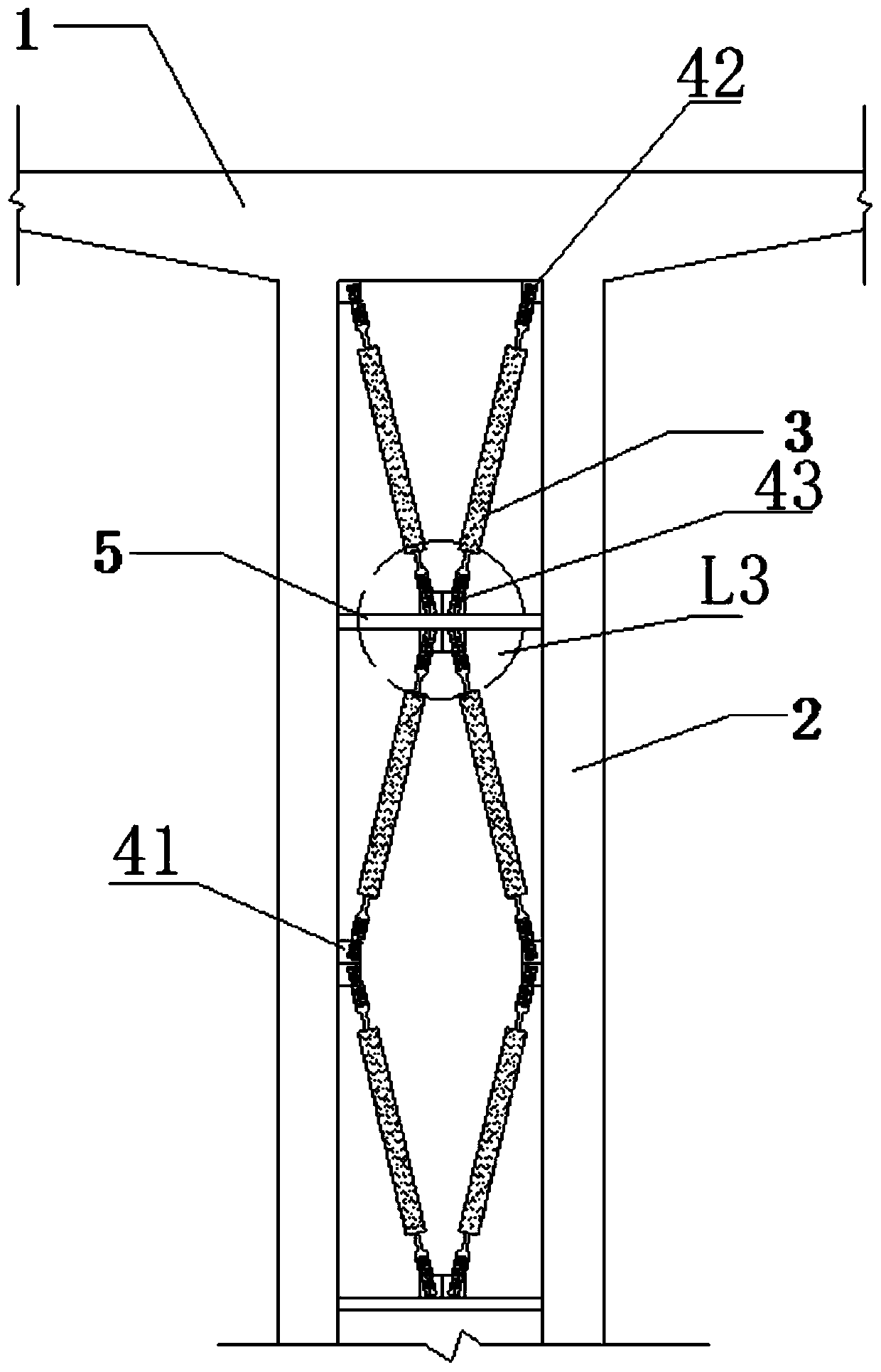
[0060] see figure 2 , a kind of shock-absorbing rigid frame bridge pier containing buckling restraint support, is characterized in that: comprise main girder 1, two limbs thin-walled piers 2, and some buckling restraint supports 3, embedded steel member 141, horizontal crossbeam 5 and some prefabricated Buried steel member III43.
[0061] The double-leg thin-walled pier 2 includes A limb 201 and B limb 202 perpendicular to the horizontal plane. Both the upper ends of the A limb 201 and the B limb 202 are connected under the main beam 1 .
[0062] When pouring the double-leg thin-walled pier 2, several pre-embedded steel components I41 are pre-embedded inside the A-leg 201 and the B-leg 202. The part of each pre-embedded steel member I41 exposed to the concrete surface is a connecting steel plate I411.
[0063] Each of the connecting steel plates I411 on the A limb 201 is located on the surface facing the B limb 202 . Each of the connecting steel plates I411 on the B limb ...
Embodiment 3
[0069] see image 3 or Figure 4 , a kind of shock-absorbing rigid frame bridge pier containing buckling restraint support, is characterized in that: comprise main girder 1 and double limb thin-walled pier 2, and some buckling restraint support 3 and embedded steel member 141.
[0070] The double-leg thin-walled pier 2 includes A limb 201 and B limb 202 perpendicular to the horizontal plane. Both the upper ends of the A limb 201 and the B limb 202 are connected under the main beam 1 .
[0071] When pouring the double-leg thin-walled pier 2, several pre-embedded steel components I41 are pre-embedded inside the A-leg 201 and the B-leg 202. The part of each pre-embedded steel member I41 exposed to the concrete surface is a connecting steel plate I411.
[0072] Each of the connecting steel plates I411 on the A limb 201 is located on the surface facing the B limb 202 . Each of the connecting steel plates I411 on the B limb 201 is located on the surface facing the A limb 202 . ...
PUM
 Abstract
Description
Claims
Application Information