
Unlocking mechanism in handle vertical pillar

A technology in handles and handles, applied in the field of unlocking mechanisms, can solve the problems of high cost of use and barriers to popularization of fingerprint locks, and achieve the effects of simplifying use, facilitating promotion, and reducing use costs

Inactive Publication Date: 2019-05-03
吴永良
View PDF0 Cites 1 Cited by
  • Summary
  • Abstract
  • Description
  • Claims
  • Application Information

AI Technical Summary

Problems solved by technology

[0002] Fingerprint locks are welcomed by everyone because they bring great convenience to users. However, most of the existing fingerprint locks are quite different from traditional mechanical locks. They need trained professionals to install and maintain them, so that fingerprint locks have High cost of use brings obstacles to popularization

Method used


Image

  • Unlocking mechanism in handle vertical pillar
  • Unlocking mechanism in handle vertical pillar
  • Unlocking mechanism in handle vertical pillar

Examples


Embodiment

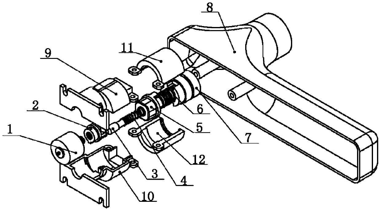
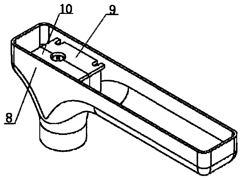
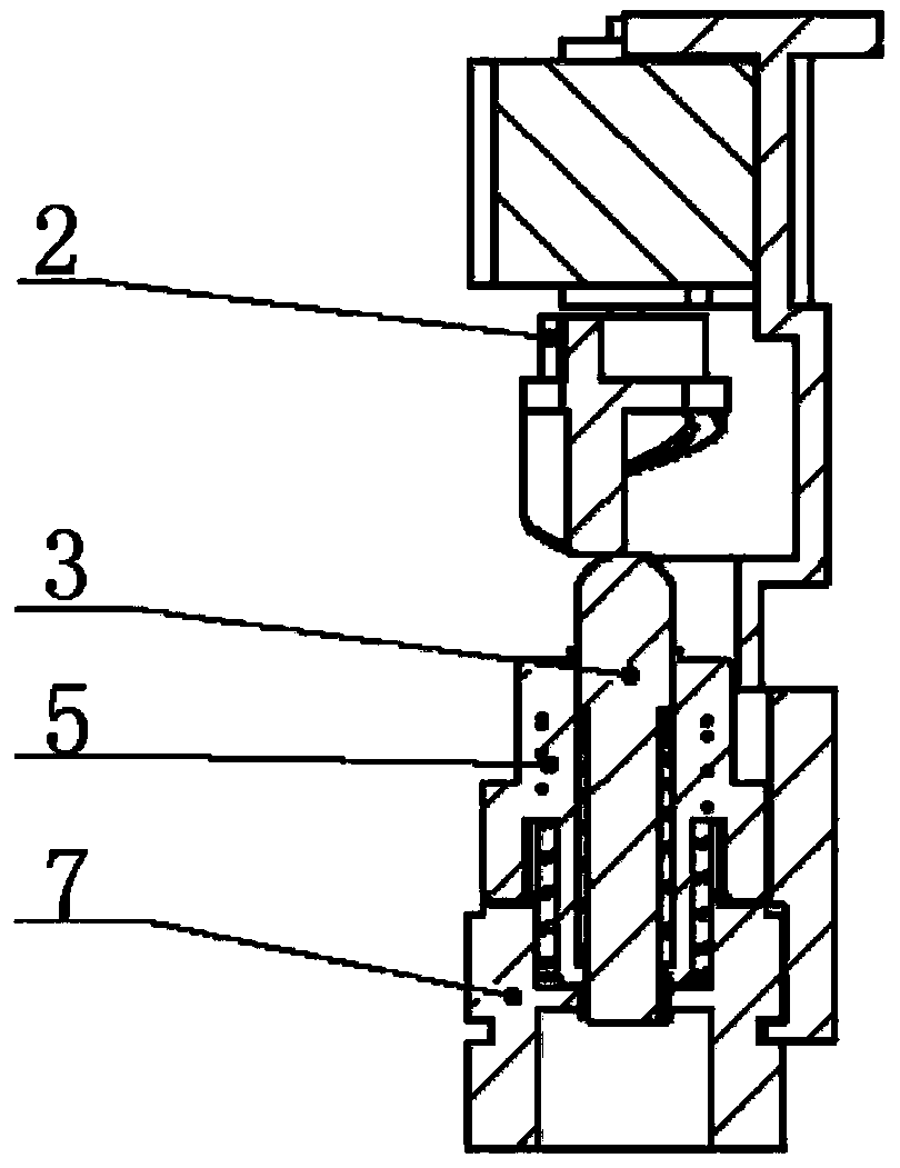
[0014] Embodiment: As shown in the accompanying drawings, this unlocking mechanism in the handle column mainly includes a stepping motor 1, a cam 2, a slide block 3, a clutch A5, and a clutch B7, and the stepping motor 1 and the cam 2 are matched and connected and can Drive it to rotate, and the slider 3 with the spring A4 on the outside is located in front of the cam 2, so that when the cam 2 rotates forward, it can push the slider 3 and compress the spring A4. One end of the clutch A5 is connected to the spring A4, and the other end is connected to the spring B6. Spring B6 links to each other with clutch B7 again, and stepper motor 1 outer cover is equipped with motor cover A9 and motor cover B10, and clutch A5 outer cover is limited cover A11 and limit cover B12, and motor cover A9 and limit cover A11, motor cover B10 and The limit cover B12 is connected with each other and fixedly installed in the handle 8. The clutch B7 is installed in the handle 8. Under the action of the...


PUM


Abstract

The invention discloses an unlocking mechanism in a handle vertical pillar. The unlocking mechanism mainly comprises a stepping motor, a cam, a sliding block, a clutch A and a clutch B; the stepping motor is connected with the cam in a matched mode and can drive the cam to rotate, the sliding block with a spring A installed on the outer part in a sleeving mode is located right ahead the cam to enable the cam to push the sliding block and compress the spring A when the cam rotate frontward, one end of the clutch A is connected with the spring A, and the other end of the clutch A is connected with a spring B; the spring B is connected with the clutch B, a motor cover A and a motor cover B are installed on the outer part of the stepping motor in sleeving mode, and a limiting cover A and a limiting cover B are installed on the outer part of the clutch A in a sleeving mode; and the motor cover A and the limiting cover A, and the motor cover B and the limiting cover B are connected in a mutually matched mode and fixedly installed in a handle, and the clutch B is installed in the handle. According to the unlocking mechanism in the handle vertical pillar, structural parts of a whole fingerprint lock is placed in the handle, the installation and use of the fingerprint lock are simplified to an utmost extent, the use cost of the fingerprint lock is reduced, and generalization and popularization of the fingerprint lock are facilitated.

Description

technical field [0001] The invention relates to the field of locks, in particular to an unlocking mechanism in a handle column. Background technique [0002] Fingerprint locks are welcomed by everyone because they bring great convenience to users. However, most of the existing fingerprint locks are quite different from traditional mechanical locks. They need trained professionals to install and maintain them, so that fingerprint locks have Larger use cost brings obstacles to popularization. Contents of the invention [0003] The purpose of the present invention is to overcome the deficiencies in the prior art, and provide an unlocking mechanism in the handle column, and place the entire structural part of the fingerprint lock in the handle. The installation and use of the fingerprint lock are simplified, the use cost of the fingerprint lock is reduced, and the promotion and popularization of the fingerprint lock are facilitated. [0004] The purpose of the present invent...

Claims


Application Information

Patent Timeline
IPC IPC(8): E05B3/00E05B47/06E05B49/00
CPCE05B3/00E05B47/06E05B49/00
Inventor 吴永良
Owner 吴永良
Learn More