Particle projection space imaging system

A space imaging and particle technology, applied in three-dimensional systems, image communication, optics, etc., can solve the problem that holographic 3D film cannot be projected in the air.

Inactive Publication Date: 2019-05-03
李超
View PDF5 Cites 2 Cited by
  • Summary
  • Abstract
  • Description
  • Claims
  • Application Information

AI Technical Summary

Problems solved by technology

[0003] The purpose of the present invention is to provide a particle projection space imaging system to solve the technical problems existing in the prior art that the spectros

Method used


Image

  • Particle projection space imaging system
  • Particle projection space imaging system
  • Particle projection space imaging system

Examples


Embodiment Construction

[0022] In order to make the technical problems, technical solutions and beneficial effects to be solved by the present invention clearer, the present invention will be further described in detail below in conjunction with the accompanying drawings and embodiments. It should be understood that the specific embodiments described here are only used to explain the present invention, not to limit the present invention.

[0023] It should be noted that when an element is referred to as being “fixed” or “disposed on” another element, it may be directly on the other element or be indirectly on the other element. When an element is referred to as being "connected to" another element, it can be directly connected to the other element or indirectly connected to the other element.

[0024] It is to be understood that the terms "length", "width", "top", "bottom", "front", "rear", "left", "right", "vertical", "horizontal", "top" , "bottom", "inner", "outer" and other indicated orientations...


PUM


Abstract

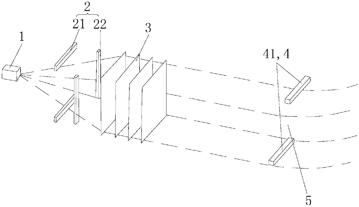
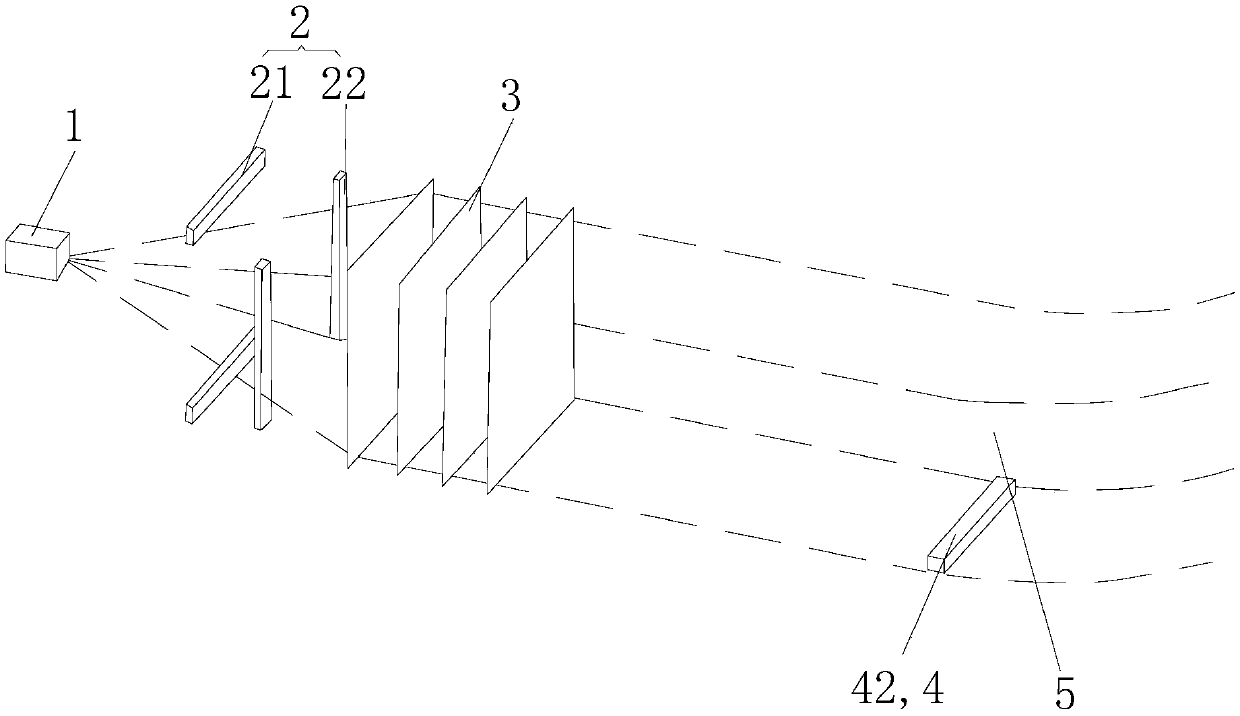
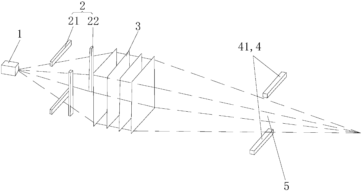
The present invention provides a particle projection space imaging system which comprises a particle source for generating and accelerating a particle beam, a deflection coil set for deflecting the particle beam into a dynamic three-dimensional particle array spreading according to a time order, an excitation coil set for generating a magnetic field, and a scanning control mechanism for controlling the particle source, the deflection coil set and the particle excitation coil set. According to the particle projection space imaging system, by setting the particle source and generating and accelerating the particle beam, the particle beam is deflected by using the deflection coil set to form the dynamic three-dimensional particle array, the particle excitation coil set excites a particle beamgroup in a corresponding pixel in the array in a time sharing manner to generate a radiation effect, and a three-dimensional image is formed. The projection space imaging system does not depend on asolid display medium and can work in air and vacuum, and a three-dimensional dynamic image can be formed by refreshing the scanning control mechanism.

Description

technical field [0001] The invention belongs to the technical field of projection imaging, and more specifically relates to a particle projection space imaging system. Background technique [0002] The current three-dimensional projection imaging technology includes spectroscopic three-dimensional display, volume three-dimensional display, holographic three-dimensional display and so on. Spectroscopic stereoscopic display means that the retina receives two images with parallax. People can "see" three-dimensional objects by distinguishing the light and shade, front and back, and distance of different areas of the object, usually through polarized light mirrors, such as three-dimensional stereoscopic glasses, three-dimensional Stereoscopic movies, etc. Volumetric 3D display uses technologies such as high-speed movement of optical devices and high-frequency light projection to synthesize multiple 2D images in a certain transparent solid to form a realistic 3D stereoscopic imag...

Claims


Application Information

Patent Timeline
IPC IPC(8): G03B35/18
CPCH04N13/39H05H7/04H05H2007/046G02B30/56H04N13/388H05H13/005
Inventor 李超
Owner 李超
Why Eureka
Try Eureka