
Textile fabric levelness cloth inspecting and checking equipment

A textile fabric and levelness technology, which is applied in the field of textile fabric levelness inspection and checking equipment, can solve the problems of large color difference detection error, being unable to be irradiated by the light source, and moving the fabric to a place other than the illuminated surface, etc., to achieve The effect of reducing the detection error

Inactive Publication Date: 2020-06-26
杭州源凯诚科技有限公司
View PDF0 Cites 0 Cited by
  • Summary
  • Abstract
  • Description
  • Claims
  • Application Information

AI Technical Summary

Problems solved by technology

[0003] Existing inspection items for fabric inspection of textile fabrics include: color difference, odor, holes, etc. Most of the existing cloth inspection equipment is driven by rollers to rotate the fabric, and the method of detecting color difference by light, but the fabric is a light material When it is driven, deflection will occur, and the deflection will cause part of the fabric to move to a place other than the illuminated surface, so it cannot be illuminated by the light source, and the error of color difference detection will be larger. Therefore, a textile fabric levelness inspection cloth check Equipment came into being

Method used


Image

  • Textile fabric levelness cloth inspecting and checking equipment
  • Textile fabric levelness cloth inspecting and checking equipment
  • Textile fabric levelness cloth inspecting and checking equipment

Examples


Embodiment Construction

[0023] The technical solutions in the embodiments of the present invention will be clearly and completely described below in conjunction with the accompanying drawings in the embodiments of the present invention. Obviously, the described embodiments are only some of the embodiments of the present invention, not all of them. Based on the embodiments of the present invention, all other embodiments obtained by persons of ordinary skill in the art without creative work all belong to the protection scope of the present invention.

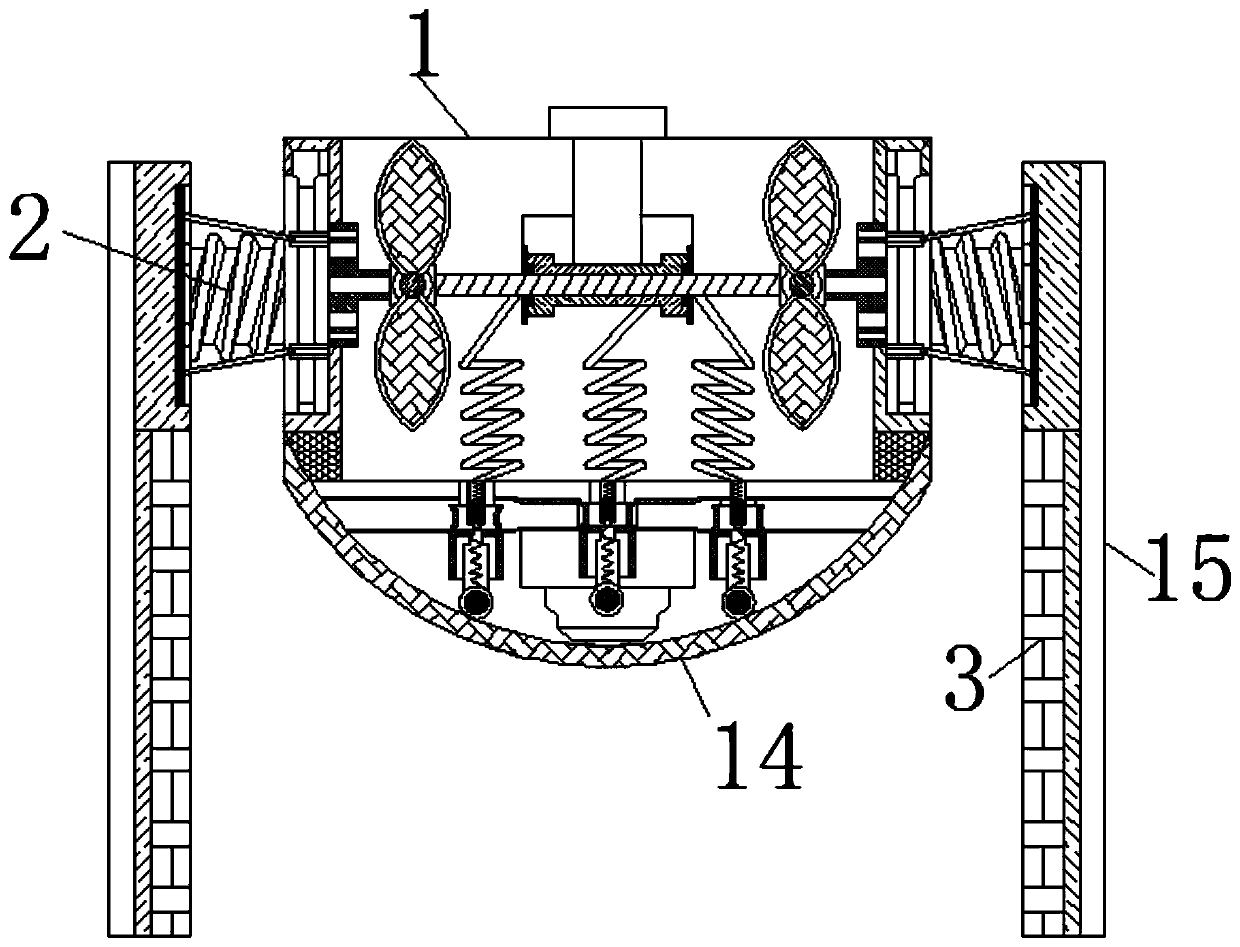
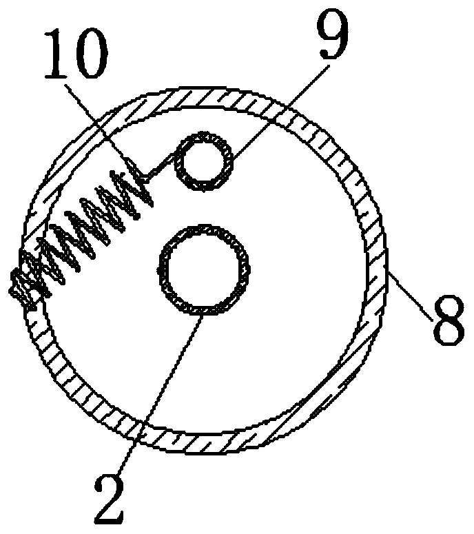
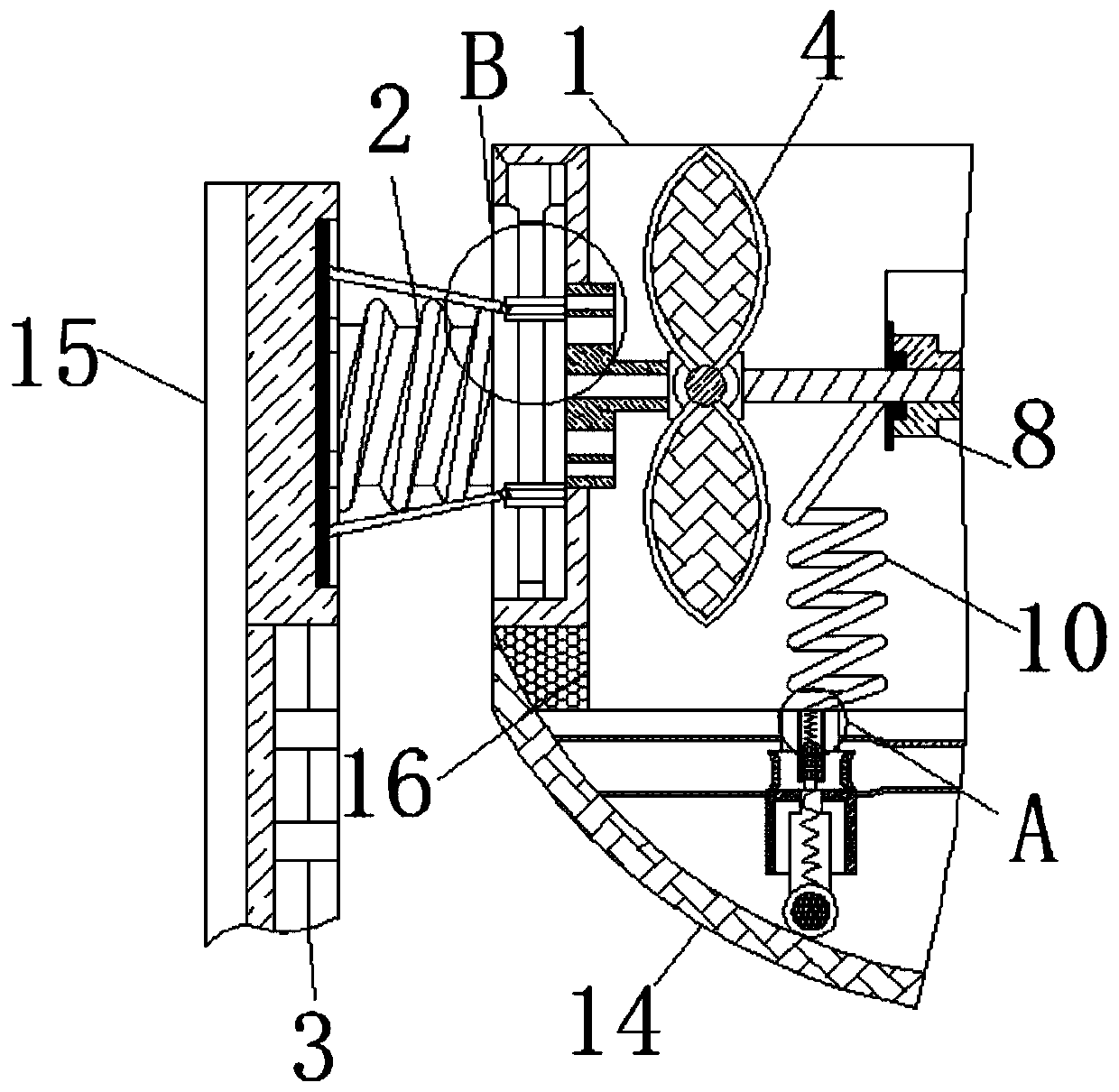
[0024] see Figure 1-7 , a kind of textile fabric levelness inspection and checking equipment, comprising a roller shaft 1, both sides of the roller shaft 1 are movably connected with a screw 2, and the end of the screw rod 2 away from the roller shaft 1 is movably connected with an air groove 3, and the air groove 3 is movably connected The surface is fixedly connected with an air deflector 15, the air deflector 15 is an arc-shaped triangle design, and ...


PUM


Abstract

The invention relates to the technical field of textile fabric cloth inspecting, and discloses textile fabric levelness cloth inspecting and checking equipment. The textile fabric levelness cloth inspecting and checking equipment comprises a roll shaft; screws are movably connected to both sides of the roll shaft; one end of each screw far away from the roll shaft is movably connected with an airduct; the surface of the inner screw of the roll shaft is movably connected with a fan blade; ventilation plates are fixedly connected to the inner two side walls of the roll shaft; a sliding chute isconfigured on the inner side wall of the roll shaft and located on the surfaces of the ventilation plates; the surface of the sliding chute is slidingly connected with a squeezing rod; the surfaces of the screws are movably connected with gears; the surfaces of the gears are movably connected with uprights; the surfaces of the uprights are movably connected with spring wires; and the other end ofeach spring wire is movably connected with a roller lever. The airflow generated by the rotation of the fan blades is guided by a wind guide plate and then is blown to the surface of the cloth, and the airflow can also blow off peculiar smell or impurities on the surface of the cloth; and the air duct and other components are symmetrically designed, so that the effect of using the wind power generated by the roll shaft rotation to clamp the cloth to maintain the levelness is achieved.

Description

technical field [0001] The invention relates to the technical field of cloth inspection of textile fabrics, in particular to a cloth checking device for the horizontality of textile fabrics. Background technique [0002] Knitted fabrics are divided into weft-knitted fabrics and warp-knitted fabrics according to the weaving method; warp-knitted fabrics are in the direction of the length of the fabric, and weft-knitted fabrics are in the direction of the width of the fabric; the manufacturing process of textile fabrics often has the following seven steps: Spinning→weaving→cloth inspection→cutting→sewing→ironing→inspection; cloth inspection is one of the more critical steps in the production of textile fabrics. [0003] Existing inspection items for fabric inspection of textile fabrics include: color difference, odor, holes, etc. Most of the existing cloth inspection equipment is driven by rollers to rotate the fabric, and the method of detecting color difference by light, but ...

Claims


Application Information

Patent Timeline
IPC IPC(8): D06H3/08D06H3/02D06G1/00
CPCD06G1/00D06H3/02D06H3/08
Inventor 何华斌
Owner 杭州源凯诚科技有限公司
Learn More