An equipment indicating lamp color identification method and system based on camera image acquisition

A technology of image acquisition and color recognition, which is applied in the field of electronic information, can solve the problems of not considering the influence of the color and brightness of the indicator light, and achieve the effect of improving the recognition accuracy and recognition efficiency

Pending Publication Date: 2019-05-03
INFORMATION & TELECOMM COMPANY SICHUAN ELECTRIC POWER
View PDF9 Cites 8 Cited by
  • Summary
  • Abstract
  • Description
  • Claims
  • Application Information

AI Technical Summary

Problems solved by technology

[0004] To sum up, when identifying the color state of the indicator light, the current method has the disadvantage of not considering the influence of factors such as external conditions such as light and the state of the indicator light itself such as color fading on the color and brightness of the indicator light

Method used


Image

  • An equipment indicating lamp color identification method and system based on camera image acquisition
  • An equipment indicating lamp color identification method and system based on camera image acquisition
  • An equipment indicating lamp color identification method and system based on camera image acquisition

Examples


Embodiment 1

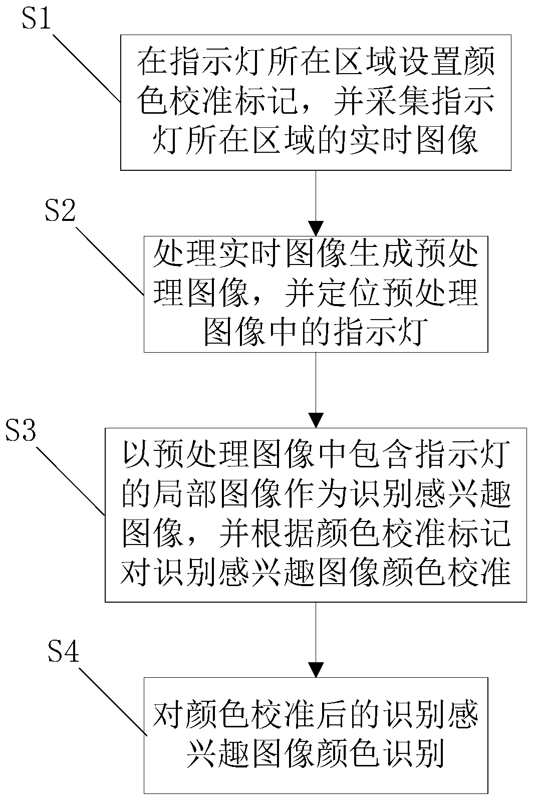
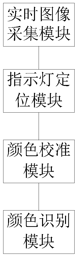
[0055] like figure 1 As shown, the method for identifying the color of the indicator light of the device based on camera image acquisition in the present invention includes: S1: setting a color calibration mark in the area where the indicator light is located, and collecting a real-time image of the area where the indicator light is located; S2: processing the real-time image to generate a pre-processed image , and locate the indicator light in the pre-processing image; S3: take the partial image containing the indicator light in the pre-processing image as the image of interest for identification, and calibrate the color of the image of interest for identification according to the color calibration mark; S4: color-calibrated Identify images of interest for color recognition.

[0056] When this embodiment is implemented, it is necessary to set a color calibration mark in the area where the indicator light is located. This color mark can be pasted on the device under test, or i...

Embodiment 2

[0059] In this embodiment, on the basis of Embodiment 1, step S1 includes the following sub-steps: calibrate the image acquisition device, and initially align the area where the indicator light is located; use the image acquisition device to collect real-time images of the area where the indicator light is located.

[0060] When this embodiment is implemented, the image acquisition device needs to be calibrated before officially acquiring the image, so as to avoid the virtual focus phenomenon from affecting the quality of the acquired image. At the same time, in order to facilitate the realization of indicator light positioning and color calibration in the subsequent steps, the device panel should be located in the center of the image as completely as possible.

Embodiment 3

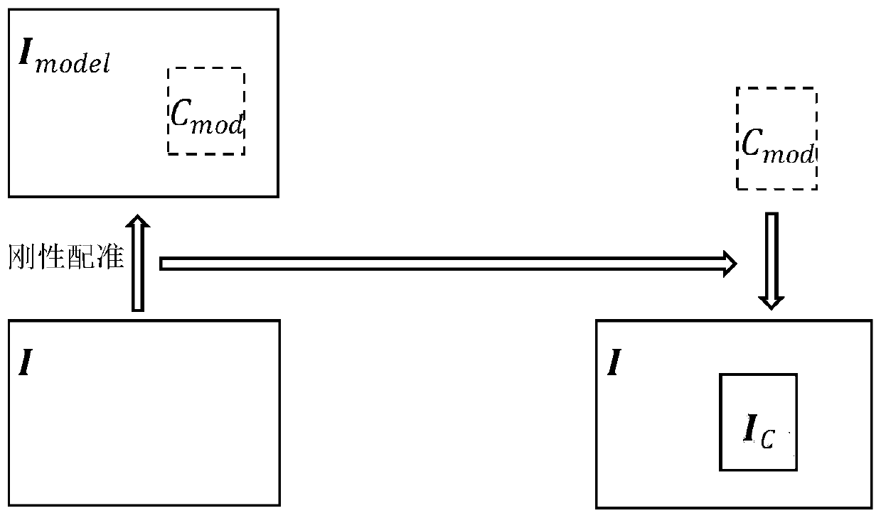
[0062] In this embodiment, on the basis of Embodiment 1, step S2 includes the following sub-steps: perform rigid matching on the real-time image according to the existing standard template image to generate a preprocessed image; the standard template image contains position information of the indicator light; The indicator light position information on the template image locates the indicator light in the preprocessed image.

[0063] During the implementation of this embodiment, in order to realize the positioning of the indicator light on the real-time acquisition image, an existing standard template image of the device to be detected in the system is required, and the position of the indicator light that has been marked needs to be placed on the standard template image. The rigid matching of the real-time image can make the position of the indicator light in the preprocessed image generated after deformation correspond to the position of the indicator light on the standard te...


PUM


Abstract

The invention discloses an equipment indicating lamp color identification method based on camera image acquisition, which comprises the following steps: S1, setting a color calibration mark in an areawhere an indicating lamp is located, and acquiring a real-time image of the area where the indicating lamp is located; S2, processing the real-time image to generate a pre-processed image, and positioning an indicator light in the pre-processed image; S3, taking a local image containing an indicator light in the preprocessed image as an identification interested image, and calibrating the color of the identification interested image according to the color calibration mark; and S4, identifying the color of the identified image of interest after color calibration. The invention also discloses an equipment indicating lamp color identification system based on camera image acquisition. According to the equipment indicating lamp color identification method and system based on camera image acquisition, the color of the indicating lamp can be accurately identified under the influence of various external and internal factors, and the identification accuracy and the identification efficiency are effectively improved.

Description

technical field [0001] The invention relates to the field of electronic information technology, in particular to a method and system for identifying the color of an indicator light of an equipment based on camera image acquisition. Background technique [0002] In the field of equipment management and maintenance in large-scale computer rooms, it is usually necessary to monitor the status of a large number of equipment, to troubleshoot equipment abnormalities in a timely manner and to deal with them accordingly. The common method is manual monitoring. Specifically, the relevant technical personnel will identify the status indicators of the equipment. The more common color distribution of the equipment indicator lights is green to indicate that the equipment is running normally, and yellow and red to indicate that the equipment is in an alarm. By manually reading the color of each indicator light to determine the current operating status of the device, so as to further mainta...

Claims


Application Information

Patent Timeline
Patent Type & Authority Applications(China)
IPC IPC(8): G06K9/36G06K9/32G06K9/00G06K9/46
Inventor 杨帆常健曾愚王鑫龚艳潘可佳
Owner INFORMATION & TELECOMM COMPANY SICHUAN ELECTRIC POWER
Why Eureka
Try Eureka