Banknote foreign object detection using pressure sensing array
A pressure sensor and banknote technology, which is applied in the measurement of the property force of the piezoelectric resistance material, the verification of the authenticity of the banknote, and the measurement force, etc., can solve the problems of damage to the banknote processing element of the automatic teller machine, etc.
- Summary
- Abstract
- Description
- Claims
- Application Information
AI Technical Summary
Problems solved by technology
Method used
Image

Examples
Embodiment Construction
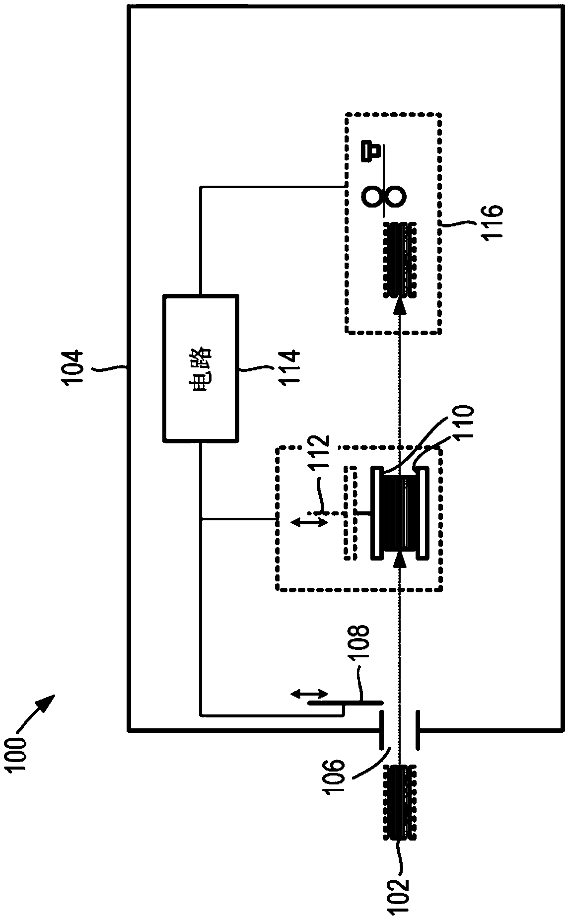
[0012] Foreign objects have the potential to damage one or more of the banknote processing components inside the ATM. For example, if two or more banknotes are stapled together, the staples may jam a mechanism that processes the banknotes one at a time. As another example, a rubber band surrounding two or more banknotes may also jam the processing mechanism.
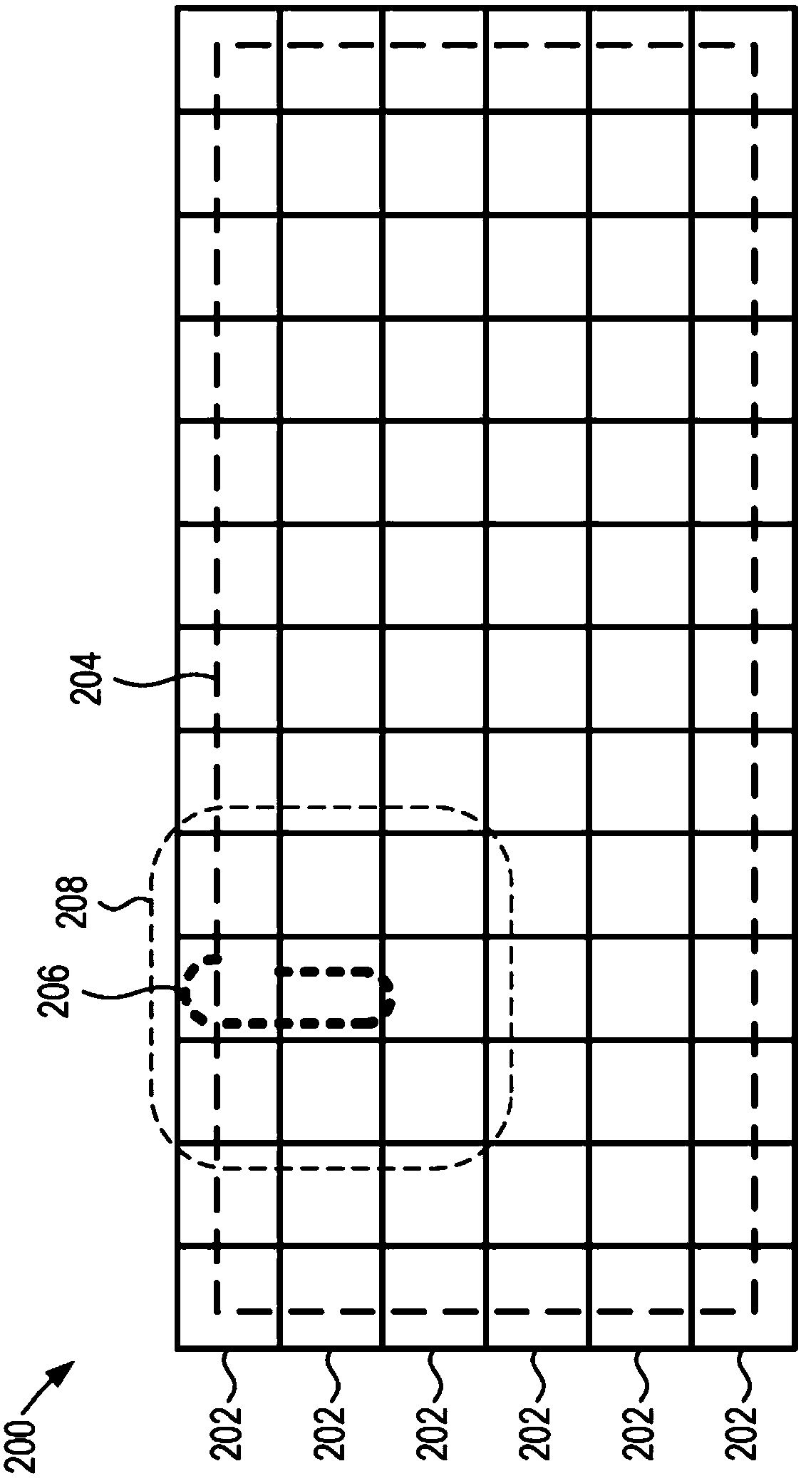
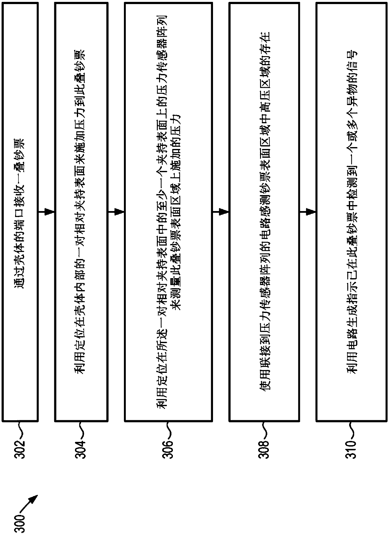
[0013] To detect these foreign objects, the system discussed below may apply pressure to a stack of banknotes. Any foreign object of appreciable thickness, such as a paper clip, staple, or rubber band, can present as an area of relatively high pressure. For example, when a stack of banknotes is under pressure, a staple at the corner of a banknote can create an area of relatively high stress at the corner of the stack.
[0014] In some examples, an ATM may use an array of pressure sensors such as piezoresistive sensors to detect the presence of foreign objects such as staples, paper clips or rubber bands in a stack ...
PUM
 Abstract
Description
Claims
Application Information
PatSnap Eureka turns technology decisions into work you can execute. Powered by our Innovation Knowledge Graph, it runs expert workflows across engineering, life sciences, materials and intellectual property. Get your review-ready output in minutes.


