Electric motor devices for switch drives for electrical switches

A technology of switch driver and electrical switch, which is applied to the power device inside the switch, electronic commutation motor control, electrical switch and other directions, which can solve the problems of increasing the cost of installing the motor and the failure rate.

Active Publication Date: 2021-03-09
SIEMENS ENERGY GLOBAL GMBH CO & KG
View PDF4 Cites 0 Cited by
  • Summary
  • Abstract
  • Description
  • Claims
  • Application Information

AI Technical Summary

Problems solved by technology

Component and wiring changes increase the cost and failure rate of installed motors

Method used


Image

  • Electric motor devices for switch drives for electrical switches
  • Electric motor devices for switch drives for electrical switches
  • Electric motor devices for switch drives for electrical switches

Examples


Embodiment Construction

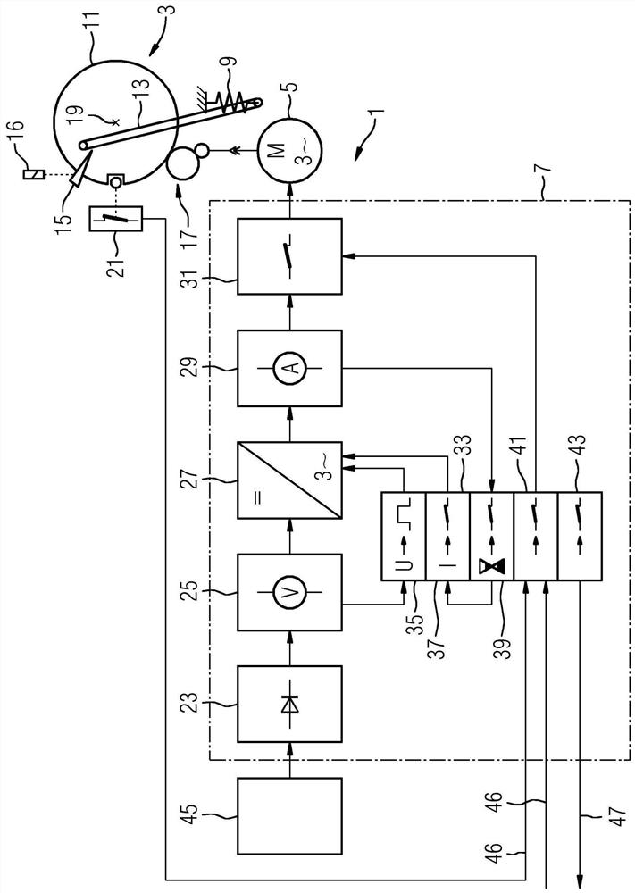
[0027] figure 1 A block diagram of a switch driver 3 of an electrical switch and a block diagram of an electric motor arrangement 1 for the switch driver 3 are shown. The motor arrangement 1 has a brushless three-phase motor 5 and an electronic control unit 7 for controlling the three-phase motor 5 . The switch drive 3 is a spring energy drive and has a spring 9 , a tensioning wheel 11 , a coupling element 13 connecting the spring 9 to the tensioning wheel 11 , a locking unit 15 and a triggering unit 16 .

[0028] The three-phase electric motor 5 is coupled to the tensioning wheel 11 via a transmission mechanism 17 , so that the tensioning wheel 11 rotates in a first direction of rotation about an axis of rotation 19 from a first end position to a second end position. The coupling element 13 is embodied as a coupling rod which is connected at one end to the tensioning wheel 11 and at the other end to the spring 9 , so that the spring 9 is tensioned by rotation of the tensioni...


PUM


Abstract

The invention relates to an electric motor arrangement (1) for a switch drive (3) of an electrical switch. The motor device (1) comprises a brushless three-phase motor (5) and an electronic control device (7) for controlling the three-phase motor (5). The control device (7) has a rectifier unit (23) for rectifying the supply voltage (U1, U2) of the motor device (1) when the supply voltage (U1, U2) is an alternating voltage, and for rectifying the supply voltage (U1, U2) when the supply voltage (U1, U2) , U2) is protected against reverse polarity when it is a DC voltage. In addition, the control device (7) has a voltage measurement unit (25) for collecting the rectifier output voltage of the rectifier unit (23); for generating a pulse-width-modulated driving AC for the three-phase motor (5) according to the rectifier output voltage a voltage switching unit (27); and a control unit (33) for controlling the switching unit (27) according to the output voltage of the rectifier.

Description

technical field [0001] The invention relates to an electric motor arrangement for a switch drive of an electrical switch and to a method for operating the same. Background technique [0002] Electrical switches used to make or break current paths of medium and high voltages and currents require large mechanical energy to move the switch contacts of the switch. [0003] For example, to move the switch contacts of a circuit breaker, a switch actuator with stored mechanical energy, such as a spring stored energy drive mechanism, is often used. In a spring stored energy drive mechanism, a spring, such as a helical spring, is usually tensioned through a transmission using an electric motor. The spring is locked against voluntary relaxation so that energy remains stored in the spring. Via the trigger, the stored energy can be released by unblocking the spring, thereby allowing the spring to relax. Thus, a switching action can be carried out by means of the available stored ener...

Claims


Application Information

Patent Timeline
Patent Type & Authority Patents(China)
IPC IPC(8): H01H3/30H02P6/08H01H3/26H02P27/08H02P7/03
CPCH01H3/30H01H3/3005H01H3/3021H01H2003/266H02P6/085H02P27/08H01H3/26H02P7/03
Inventor T.希尔克
Owner SIEMENS ENERGY GLOBAL GMBH CO & KG
Why Eureka
Try Eureka