Positioning method based on arrival time and angle of arrival

A positioning method and time-of-arrival technology, applied in the field of wireless positioning, can solve problems such as complex positioning methods, and achieve the effect of simple positioning methods

Pending Publication Date: 2019-05-07
SHENZHEN RES INST THE CHINESE UNIV OF HONG KONG
View PDF4 Cites 4 Cited by
  • Summary
  • Abstract
  • Description
  • Claims
  • Application Information

AI Technical Summary

Problems solved by technology

[0003] In order to solve the complex technical problems of the above positioning methods, the

Method used


Image

  • Positioning method based on arrival time and angle of arrival
  • Positioning method based on arrival time and angle of arrival
  • Positioning method based on arrival time and angle of arrival

Examples


Embodiment Construction

[0031] The present invention will be further described below with reference to the accompanying drawings and in combination with preferred embodiments.

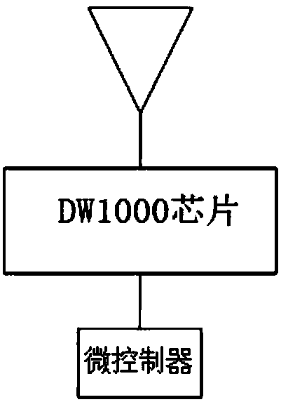
[0032] see figure 1 , a diagram of an embodiment of a transmitter system based on time-of-arrival and angle-of-arrival positioning.

[0033] Here the transmitter uses a commercial chip DW1000 to send TOA signals and DOA single-frequency signals. In other embodiments, other types of chips can also be used. This chip is connected to the antenna, which is equivalent to a receiver, and uses a microcontroller (MCU) for Communication protocol control. When carrying out the TOA test, the DW1000 in the transmitter sends an ultra-wideband (ultra-wideband, UWB) signal; when carrying out the DOA test, the transmitter sends a single-frequency signal, which can also be a modulated signal or an ultra-wideband signal in other embodiments .

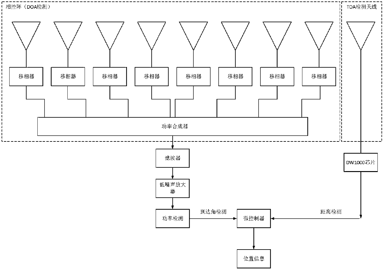
[0034] see figure 2 , Block diagram of receiver system for joint TOA-DOA positioning.

[0035]...


PUM


Abstract

The invention discloses a positioning method based on arrival time and angle of arrival. The method comprises the steps that S1 a receiver receives a signal sent by a transmitter, detects the power ofthe signal, and acquires the incoming wave angle of the transmitter according to the power; S2 the receiver detects the transmission delay of the transmitter transmitting an ultra-wideband signal, and calculates the distance between the receiver and the transmitter according to the transmission delay; and S3 according to the incoming wave angle in the step S1 and the distance in the step S2, thelocation of the transmitter is determined. The positioning method is simple.

Description

technical field [0001] The invention relates to the field of wireless positioning, in particular to a positioning method based on arrival time and arrival angle. Background technique [0002] Traditional indoor wireless positioning is generally divided into two types, one is based on arrival time, and the other is based on arrival angle. Time-of-arrival positioning calculates the distance to the transmitter according to the arrival time of each receiver, so as to determine the position of the transmitter. Generally, the number of receivers is three. The angle of arrival obtains the position of the transmitter according to the angle of the transmitter obtained by each receiver, and at least two receivers are required. Both of these two wireless positioning methods require multiple receivers, and there is a problem that the positioning method is complicated. Contents of the invention [0003] In order to solve the complicated technical problem of the above positioning meth...

Claims


Application Information

Patent Timeline
IPC IPC(8): G01S5/04G01S5/06
Inventor 吴克利韦大成范海军林浩洪荣鸿
Owner SHENZHEN RES INST THE CHINESE UNIV OF HONG KONG
Why Eureka
Try Eureka