

In-wall electrical control box
A technology for electrical control boxes and electrical boxes, applied in the direction of electrical components, etc., can solve the problem that the number of bushings cannot be adjusted, and achieve the effect of expanding the available support surface, improving strength, and avoiding left and right shaking
- Summary
- Abstract
- Description
- Claims
- Application Information
AI Technical Summary
Problems solved by technology
Method used
Image

Examples
Embodiment 1
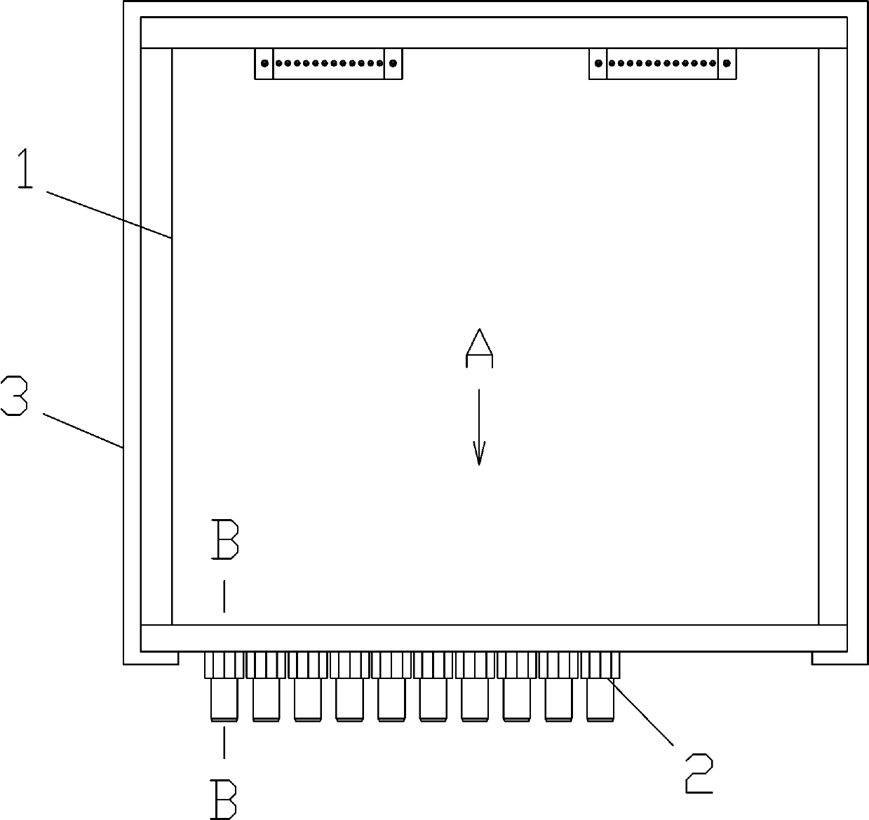
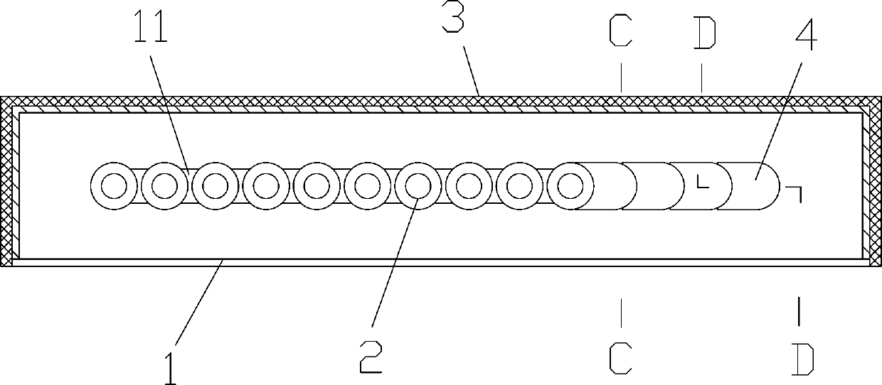
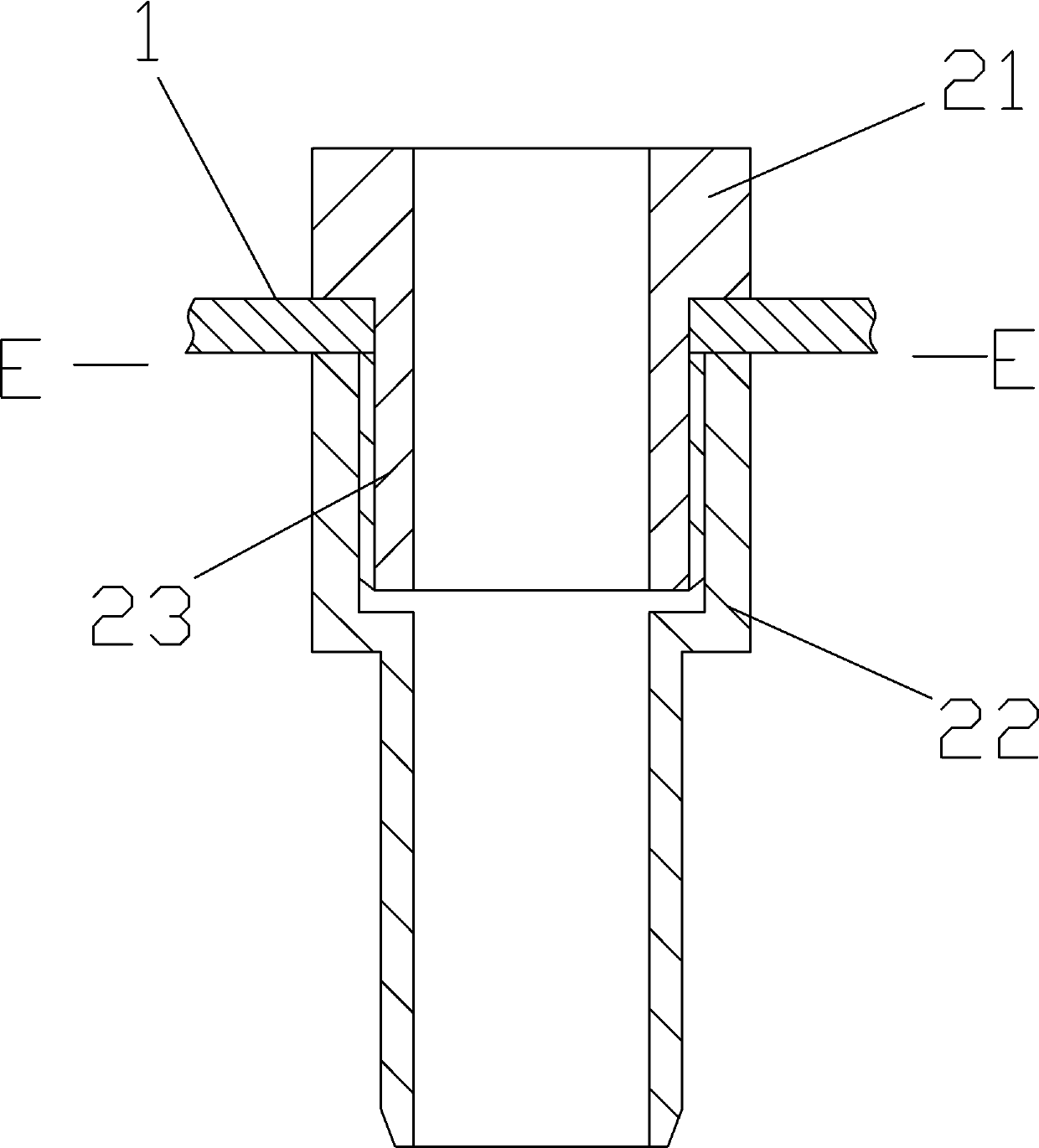
[0029] Such as Figures 1 to 3 As shown, an electrical control box in a wall includes a main body of the electrical box 1, and a waist-shaped hole 11 is provided at the bottom of the electrical box 1, and a plurality of sleeves 2 are installed in the waist-shaped hole 11, and the sleeves 2 include male A sleeve 21 and a female sleeve 22, one end of the male sleeve 21 is connected with a section of screw tube 23, the screw tube 23 is connected in the female sleeve 22, and the outer wall of the electrical box 1 on both sides of the waist hole 11 is pressed between the male sleeve 21 and the female sleeve 22 between.
[0030] This patent can freely adjust the number of sleeves 2 according to engineering needs, so as to meet the demand for sleeves 2 during actual construction, and avoid the phenomenon that the sleeves 2 are not enough during construction or leave a spare sleeve 2 after construction.
Embodiment 2
[0032] Embodiment 2 is a further improvement made on the basis of Embodiment 1, as Figures 1 to 6 As shown, a plurality of clamping pieces 4 are arranged and installed sequentially in the waist-shaped hole 11, a locking groove 43 is provided on both sides of the clamping piece 4, and one end of the clamping piece 4 has an arc-shaped protruding section 41, The other end of the snap-in piece 4 has a notch section 42 opposite to the protruding section 41. The edges of the protruding section 41 and the notch section 42 are all stepped. At this time, the outer walls of the electrical box 1 on both sides of the waist-shaped hole 11 are respectively snapped into the slots 43 of the snap-in pieces 4, and between two adjacent snap-in sheets 4, the protruding section 41 of one of the snap-in sheets 4 is overlapped. The other piece of snap-in piece 4 is inside the notch section 42 . The clamping piece 4 is made of elastic hard plastic, and the clamping piece 4 is clamped into the waist...
Embodiment 3
[0035] Embodiment 3 is a further improvement made on the basis of Embodiment 1, as Figures 8 to 10 As shown, it also includes a strip plate 5, the strip plate 5 is covered on the waist hole 11, and a plurality of through holes are arranged on the strip plate 5, and each sleeve pipe 2 is installed in each through hole, A rubber pad 7 is provided between the strip plate 5 and the outer wall of the electrical box 1 . After the sleeve pipe 2 is installed in each through hole on the strip plate 5, some through holes will be spared, and the remaining through holes will be blocked by the cover 6. The cover 6 includes screws 61 and nuts 62 .
[0036] The strip plate 5 can seal the waist hole 11 to prevent external moisture from entering the electrical box 1. On the other hand, the strip plate 5 can act as a gasket to expand the available supporting surface of the male sleeve 21 and the female sleeve 22. , improve the reliability of casing 2.
PUM
 Abstract
Description
Claims
Application Information