
Tunnel inspection robot

A technology for inspection robots and tunnels, applied in manipulators, manufacturing tools, etc., can solve the problem of increased maintenance costs for inspection robots, and achieve the effects of reliable inspection results, stable walking, and guaranteed accuracy.

Pending Publication Date: 2019-05-10
SICHUAN GUORUAN SCI & TECH DEV CO LTD
View PDF0 Cites 0 Cited by
  • Summary
  • Abstract
  • Description
  • Claims
  • Application Information

AI Technical Summary

Problems solved by technology

[0005] The purpose of the present invention is to solve the technical problems of the prior art tunnel inspection robot that the positioning is inaccurate, the walking instability affects the inspection results, and the inspection robot is easy to roll over and increase the maintenance cost. The present invention provides a tunnel inspection robot, The tunnel inspection robot can be accurately positioned and walks smoothly, achieving the purpose of ensuring reliable inspection results and reducing maintenance costs

Method used


Image

  • Tunnel inspection robot
  • Tunnel inspection robot
  • Tunnel inspection robot

Examples


Embodiment 1

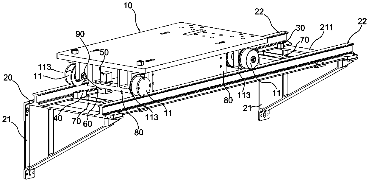
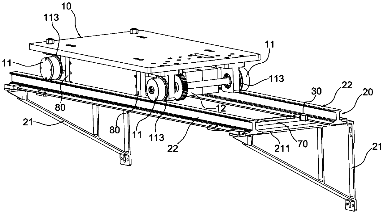
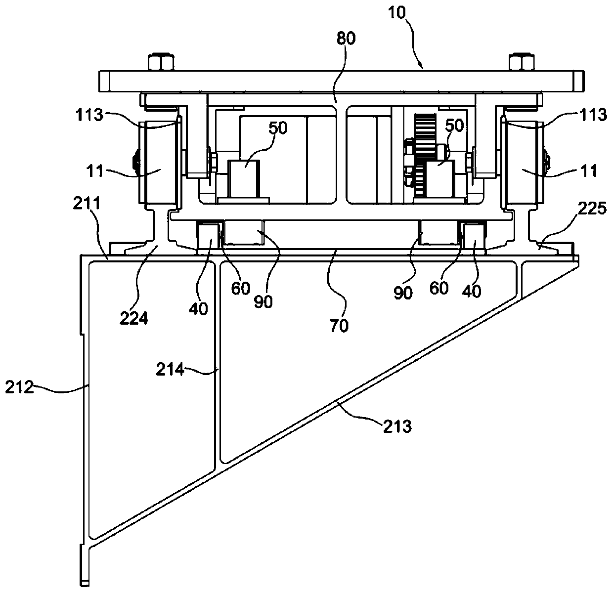
[0033] Example 1, such as Figure 1 to Figure 8 As shown, a tunnel inspection robot includes an inspection instrument, a walking trolley 10 and a mounting member 20 for installing the traveling trolley 10. The seat 21 and two parallel rails 22 overlapped on the top of the support 21, the track 22 is provided with a protrusion 221 on the upper part of the track and a protrusion 222 on the lower part of the track; several parallel connecting plates are connected between adjacent supports 21 70, the two ends of the connecting plate 70 are provided with ear plates 71, the top surface of the connecting plate 70 is higher than the top surface of the ear plate 71, the track 22 is arranged on the ear plate 71 close to the connecting plate 70; the walking trolley 10 is erected on the track 22 , the two ends of the walking trolley 10 are provided with a pair of support plates 80 stretching between the two tracks 22, and the support plate 80 both sides are provided with a support plate p...

Embodiment 2

[0037] Embodiment 2, on the basis of Embodiment 1, the traveling trolley 10 is provided with a roller 11 , the roller 11 is movably arranged on the track 22 , and the roller 11 is driven by a servo motor 12 arranged on the traveling trolley 10 . One side of the roller 11 is provided with a roller positioning convex plate 113 whose lower end extends to the side of the upper protrusion 221 of the track, and the surface of the roller 11 is covered with a layer of nylon material. By setting the roller positioning convex plate 113, the position of the roller 11 can be limited, the roller 11 can be prevented from deviating from the track 22, and the traveling trolley 10 can be guaranteed to run smoothly. The surface of the roller 11 is covered with a nylon material layer, which can reduce the noise generated when the walking trolley 10 moves.

Embodiment 3

[0038] Embodiment 3, on the basis of Embodiment 1 or 2, the impact block 40 is arranged on the connecting plate 70 . The support plate 80 is provided with a support plate hollow opening 81, and the two-way rotating electromagnet 50 is arranged in the support plate hollow opening 81 of one of the support plates 80, and the rotating shaft of the two-way rotating electromagnet 50 passes through the support plate 80 and the rotation below the support plate 80 The stopper 60 is connected. The quantity of two-way rotating electromagnet 50 is two, and two two-way rotating electromagnets 50 are respectively arranged on support plate 80 two ends, and the rotating shafts of two two-way rotating electromagnets 50 are all connected with rotating stopper 60, and the quantity of collision block 40 is Two collision blocks 40 and rotating blocks 60 are correspondingly arranged at both ends of the connecting plate 70. When the traveling trolley 10 moves, the two collision blocks 40 collide wit...


PUM


Abstract

The invention discloses a tunnel inspection robot. The tunnel inspection robot comprises an inspection instrument, a moving trolley and a mounting component, wherein the mounting component comprises asupporting seat and tracks; an upper bump and a lower bump are arranged on each track; the moving trolley is arranged on the tracks; a pair of supporting plates which extend between the tracks is arranged at two ends of the moving trolley; supporting plate positioning bumps which extend to the lower parts of the upper bumps of the tracks are arranged at two sides of the supporting plates; sensorsfor monitoring the location of the moving trolley are arranged on the tracks; impacting blocks which are in fixed distance relative to the sensors are arranged between the tracks; a two-way rotatingelectromagnet is arranged on the moving trolley; a rotating shaft of the two-way rotating electromagnet is connected to a rotating stopping block; when the moving trolley moves to the location of theimpacting blocks, the impacting blocks impact the rotating stopping block, and thus the moving trolley is stopped; and the moving trolley is provided with a controller which is combined with the sensors to control the moving state of the moving trolley as well as the rotating direction of the two-way rotating electromagnets. The tunnel inspection robot has the technical effects of accurate positioning and stable moving.

Description

technical field [0001] The invention relates to the field of tunnel inspection equipment, in particular to a tunnel inspection robot. Background technique [0002] In order to comprehensively, systematically and dynamically control the technical status of tunnels in operation (such as railway tunnels, highway tunnels, and subway tunnels), discover defects in time and formulate corresponding maintenance countermeasures to ensure safe operation of tunnels, strict tunnel inspection work is essential . [0003] Currently, manual paper records and photographic sampling are still the main means of tunnel inspection. However, there are many dangerous factors in operating tunnels, which seriously threaten the safety of inspectors. Therefore, the use of tunnel inspection robots to replace manual inspections can reduce the use of labor and avoid casualties caused by tunnel inspections. [0004] According to the requirements of tunnel inspection standards, when some tunnel inspection...

Claims


Application Information

Patent Timeline
IPC IPC(8): B25J11/00B25J5/02B25J19/00
Inventor 秦福林杨海峰袁志明石磊李娟钱鹏周益母琮玉蔡福鑫
Owner SICHUAN GUORUAN SCI & TECH DEV CO LTD
Learn More