Electric energy meter turnover cabinet with detection function

A technology of electric energy meter and turnover cabinet, which is applied in the directions of transportation, packaging, storage devices, etc., can solve the problems of not having the function of automatically judging the verification date of electric energy meters, the work efficiency, the quality improvement is not large, and the work efficiency is reduced, so as to save Chassis space, saving time and labor, and improving efficiency

Active Publication Date: 2019-05-10
STATE GRID SHANDONG ELECTRIC POWER +1
View PDF10 Cites 2 Cited by
  • Summary
  • Abstract
  • Description
  • Claims
  • Application Information

AI Technical Summary

Problems solved by technology

However, the electric energy meter turnover cabinet only realizes the outbound and inbound work of electric energy meters, and does not greatly improve the actual work efficiency and quality, so the utilization rate is not high
At present, the State Grid Corporation has strict regulations on the use time of qualified electric energy meters in the warehouse, requiring that it should not exceed 180 days from the date of verification to the date of operation. At present, the turnover cabinets configured by grassroots teams and power supply stations do not have the ability to automatically determine the verification date of electric energy meters. The function must be screened one by one in the warehouse before each replacement work, which greatly reduces the work efficiency, and a little carelessness may cause the electric energy meter to be overdue

Method used


Image

  • Electric energy meter turnover cabinet with detection function
  • Electric energy meter turnover cabinet with detection function
  • Electric energy meter turnover cabinet with detection function

Examples


Embodiment Construction

[0031] The following will clearly and completely describe the technical solutions in the embodiments of the present invention with reference to the accompanying drawings in the embodiments of the present invention. Obviously, the described embodiments are only some of the embodiments of the present invention, not all of them. Based on the embodiments of the present invention, all other embodiments obtained by persons of ordinary skill in the art without making creative efforts belong to the protection scope of the present invention.

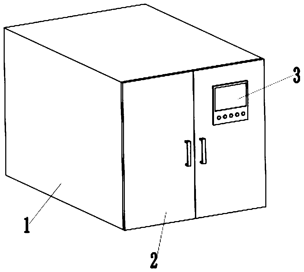
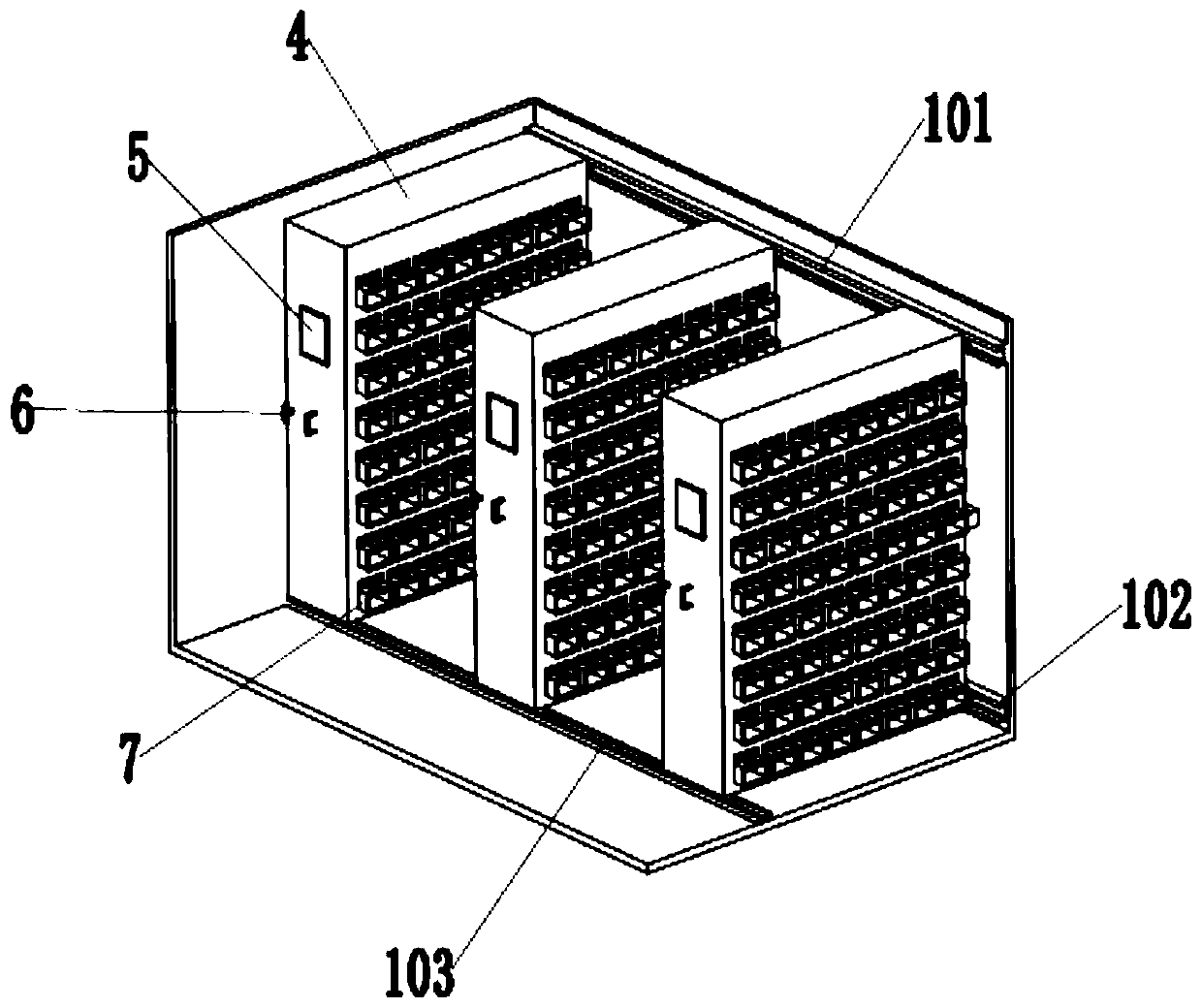
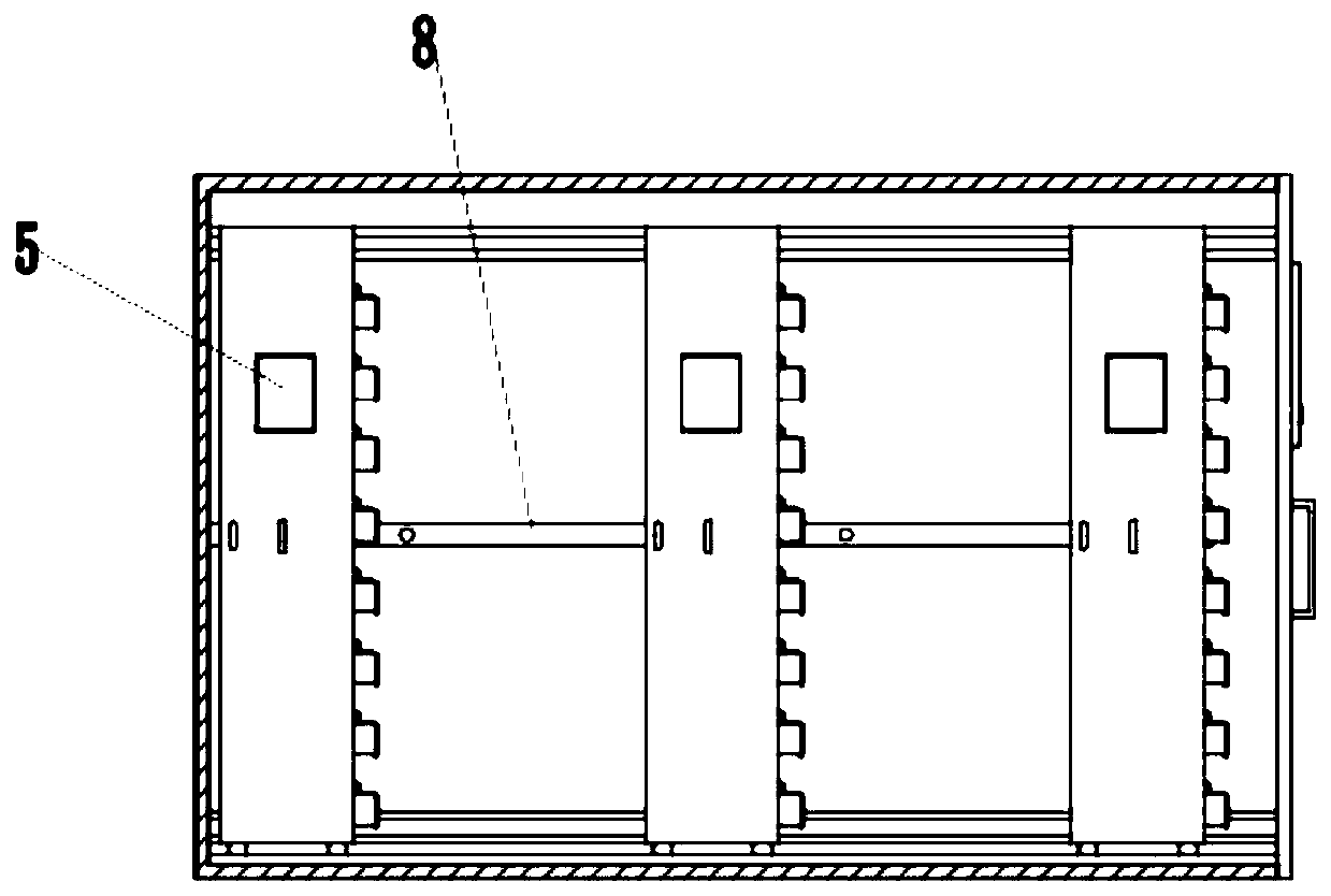
[0032] Such as figure 1 , 2 As shown, a turnover cabinet for electric energy meters with a detection function includes a cabinet 1, a storage cabinet 4, and a detection device 9. The end of the cabinet 1 is provided with a cabinet door 2, and the cabinet 1 is provided with a storage cabinet 4. Described storage cabinet 4 is provided with storage box 7, as Figure 5 As shown, the detection device 9 includes a circuit board 901, an indicator ligh...


PUM


Abstract

The invention discloses an electric energy meter turnover cabinet with a detection function. The electric energy meter turnover cabinet comprises a machine case and a storage cabinet, wherein the storage cabinet is arranged in the machine case, and a storage box is arranged on the storage cabinet. The electric energy meter turnover cabinet further comprises a detection device. The detection devicecomprises a circuit board, an indicating lamp, a power-off switch, a bar code scanner and an electromagnet, wherein the indicator lamp and the power-off switch are arranged on the circuit board, andthen bar code scanner is arranged on the upper inner wall of the storage box; the electromagnet is arranged on the portion, close to an opening of the lower end face of the storage box, and the electromagnet is electrically connected with the power-off switch; a box cover is arranged at the front end of the storage box, and a metal block is arranged at the lower end of the inner side wall of the box cover; one side of the storage cabinet is provided with a subcabinet control panel, and a main control panel is arranged on a cabinet door; and the subcabinet control panel and the main control panel each comprises a display screen, the subcabinet control panel is electrically connected with the main control panel, and the power-off switch, the indicating lamp and the bar code scanner are electrically connected with the subcabinet control panel.

Description

technical field [0001] The invention relates to the technical field of turnover cabinets, in particular to a turnover cabinet for electric energy meters with a detection function. Background technique [0002] At present, the electric power marketing department has configured electric energy meter turnover cabinets for grass-roots metering teams and power supply stations, which can realize automatic storage and collection of electric energy meters, and form a systematic management system. However, the electric energy meter turnover cabinet only realizes the delivery and storage of electric energy meters, and does not improve the actual work efficiency and quality greatly, so the utilization rate is not high. At present, the State Grid Corporation has strict regulations on the use time of qualified electric energy meters in the warehouse, requiring that the period from the date of verification to the date of operation should not exceed 180 days. At present, the turnover cabin...

Claims


Application Information

Patent Timeline
Patent Type & Authority Applications(China)
IPC IPC(8): B65G1/02
Inventor 程晓云王琦刘顺华薛中洲翟滢李海舰张纪杰张昆孔祥清张文哲胡强陈祥谋李毅孟海涛苗鹏超吴东
Owner STATE GRID SHANDONG ELECTRIC POWER
Why Eureka
Try Eureka