A multi-station braiding method

A multi-station, twisting technology, applied in the field of textile twisting, can solve the problems of unable to transport the hinged frame, unable to adjust the placement position of the hinged frame, etc.

Active Publication Date: 2020-10-27
YIBIN HIEST FIBER +1
View PDF7 Cites 0 Cited by
  • Summary
  • Abstract
  • Description
  • Claims
  • Application Information

AI Technical Summary

Problems solved by technology

[0013] In order to solve the above-mentioned problems in the prior art, the present invention proposes a multi-station braiding method, aiming at solving the problems that the twisting frame cannot be transported and the placement position of the twisting frame cannot be adjusted

Method used


Image

  • A multi-station braiding method
  • A multi-station braiding method
  • A multi-station braiding method

Examples


Embodiment 1

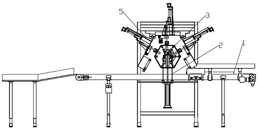
[0140] This embodiment discloses a multi-station braiding method, including a twisting frame conveying station 1, a twisting frame lifting station 2, a twisting frame rotating station 3, a twisting wire feeding station 409, and a twisting station 5.

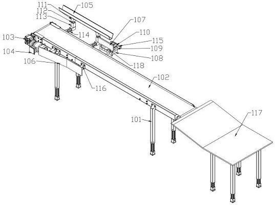
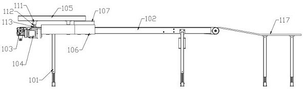
[0141] The twisted frame is placed on the conveyor belt 102, and the rollers 122 of the twisted frame are placed inside the guide groove 105 arranged along the conveying direction of the conveyor belt 102;

[0142] During the transportation process of the twisted frame, the vertically arranged regular inclined plate 106 limits one end of the twisted frame; the regular splint 107 moving in the horizontal direction regulates the other end of the twisted frame, so as to keep the two ends of the twisted frame in the conveying process in line with the other end of the twisted frame. The conveyor belts 102 are parallel.

[0143] Cylinder Ⅰ 202 drives cylinder guide rod Ⅰ 204 to lift upward, and cylinder Ⅱ 203 drives cylinder guide rod...

Embodiment 2

[0152] The twisted frame includes a hexagonal wooden frame 120, a central shaft 121 is set through the hexagonal wooden frame 120, and a roller 122 is provided at one end of the central shaft 121; 123.

[0153] This embodiment discloses a multi-station braiding machine, which includes a kink frame conveying station 1 , a kink frame lifting station 2 and a kink frame rotating station 3 .

[0154]Described winch conveying station 1 comprises the conveyer belt mechanism that is arranged on the belt conveyor frame 101, and described conveyer belt mechanism comprises conveyer belt 102 and the belt conveying speed reducer 103 that is connected with conveyer belt 102 and belt conveying motor 104; Said conveyer belt The mechanism also includes a guide groove 105 arranged along the conveying direction of the conveyor belt 102, the guide groove 105 is located on one side of the conveyor belt 102, and a vertically arranged regular inclined plate 106 is arranged on the other side of the c...

Embodiment 3

[0160] The twisted frame includes a hexagonal wooden frame 120, a central shaft 121 is set through the hexagonal wooden frame 120, and a roller 122 is provided at one end of the central shaft 121; 123.

[0161] This embodiment discloses a multi-station braiding machine, which includes a kink frame conveying station 1 , a kink frame lifting station 2 and a kink frame rotating station 3 .

[0162] Twisted frame conveying station 1 comprises the conveyer belt mechanism that is arranged on the belt conveyer frame 101, and described conveyer belt mechanism comprises conveyer belt 102 and is connected with conveyer belt 102 belt conveying speed reducer 103 and belt conveying motor 104; Described conveyer belt mechanism also It includes a guide groove 105 arranged along the conveying direction of the conveyor belt 102, the guide groove 105 is located on one side of the conveyor belt 102, and the other side of the conveyor belt 102 is provided with a vertically arranged regular inclin...


PUM


Abstract

The embodiment of the invention discloses a multi-station weaving and twisting method and belongs to the technical field of spinning and twisting. Existing automatic weaving and twisting machines areautomated in a working process after twisting frames are placed to regulated positions. The problem how to transport the twisting frame and adjust the placing direction of the twisting frame is not solved as well by a mounting seat of the twisting frame. A twisting frame transporting station, a twisting frame lifting station, a twisting frame rotating station and a twisting station are included. The twisting frame can be transported to the weaving and twisting position automatically and automatic weaving and twisting work is carried out automatically.

Description

technical field [0001] The invention relates to the technical field of textile twisting, in particular to a multi-station twisting method. Background technique [0002] At present, after the silk threads in the textile industry at home and abroad are twisted, almost all of them adopt the method of manual twisting. The existing manual twisting actions include: [0003] 1. To feed the bottom thread, the operator uses one hand to pull the silk thread drawn from the silk cake from the center of the skein frame waiting to be twisted, and pass from the bottom of the thread to the end. [0004] 2. To hook the bottom thread, the operator uses the finger of the other hand to insert the gap between the silk threads separated by the stranding machine on the twisting frame, and hook out the bottom thread, so that the bottom thread is formed on the finger above the silk thread. [0005] 3. The operator rewinds the end of the bottom thread at the end and passes through the loop formed by...

Claims


Application Information

Patent Timeline
Patent Type & Authority Patents(China)
IPC IPC(8): D04G5/00D04B33/00
Inventor 贺敏杨壬康张其凤方叶
Owner YIBIN HIEST FIBER
Why Eureka
Try Eureka