
A twist frame conveying lifting and rotating device for braiding machine

A technology of a rotating device and a lifting device, which is applied in the field of textile twisting, can solve the problems such as the inability to twist the frame and the adjustment of the placement position of the twisted frame.

Active Publication Date: 2020-10-13
YIBIN HIEST FIBER +1
View PDF5 Cites 0 Cited by
  • Summary
  • Abstract
  • Description
  • Claims
  • Application Information

AI Technical Summary

Problems solved by technology

[0013] In order to solve the problems existing in the above-mentioned prior art, the present invention proposes a twisting frame transport lifting and rotating device for a braiding machine, aiming at solving the problem that the twisting frame cannot be transported, lifted and rotated, and the twisting frame cannot be aligned. The problem of adjusting the placement position

Method used


Image

  • A twist frame conveying lifting and rotating device for braiding machine
  • A twist frame conveying lifting and rotating device for braiding machine
  • A twist frame conveying lifting and rotating device for braiding machine

Examples


Embodiment 1

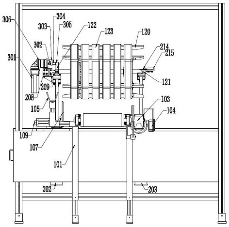
[0095] The twisted frame includes a hexagonal wooden frame 120, a central shaft 121 is set through the hexagonal wooden frame 120, and a roller 122 is provided at one end of the central shaft 121; 123.

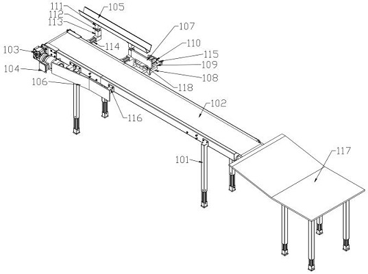
[0096] This embodiment discloses a twist frame conveying lifting and rotating device for a braiding machine, including a twist frame conveying device 1 , a twist frame lifting device 2 and a twist frame rotating device 3 .

[0097] Described winch conveying device 1 comprises the conveyer belt mechanism that is arranged on the belt conveyor frame 101, and described conveyer belt mechanism comprises conveyer belt 102 and is connected with conveyer belt 102 and the belt conveying speed reducer 103 that is connected with conveyer belt motor 104; Said conveyer belt mechanism It also includes a guide groove 105 arranged along the conveying direction of the conveyor belt 102, the guide groove 105 is located on one side of the conveyor belt 102, and the other side of the conveyor bel...

Embodiment 2

[0102] The twisted frame includes a hexagonal wooden frame 120, a central shaft 121 is set through the hexagonal wooden frame 120, and a roller 122 is provided at one end of the central shaft 121; 123.

[0103] A twist frame conveying lifting and rotating device for a braiding machine, comprising a conveyor belt mechanism arranged on a belt conveyor frame 101, the conveyor belt mechanism including a conveyor belt 102 and a belt conveyor reducer 103 connected to the conveyor belt 102 and a belt conveyor motor 104; the conveyor belt mechanism also includes a guide groove 105 arranged along the conveying direction of the conveyor belt 102, the guide groove 105 is located on one side of the conveyor belt 102, and the other side of the conveyor belt 102 is provided with a The regular inclined plate 106 that is vertically arranged; Described guide groove 105 is parallel with described conveyer belt 102; And described guide groove 105 place height is higher than described conveyer be...


PUM


Abstract

The invention discloses a twisting frame conveying, lifting and rotating device for a knitting twisting machine, and belongs to the technical field of spinning twisting. The problems that in the priorart, a twisting frame cannot be subjected to conveying, lifting and rotating, and the placement position of the twisting frame cannot be adjusted are solved. The twisting frame conveying, lifting androtating device comprises a twisting frame conveying device, a twisting frame lifting device and a twisting frame rotating device. The twisting frame conveying device conveys a twisting frame to thespecific position at first, then, the twisting frame lifting device lifts the twisting frame upwards, and finally, the twisting frame rotating device enables the twisting frame to rotate. According tothe twisting frame conveying, lifting and rotating device, a series of position adjusting of the twisting frame can be conducted, and accordingly, the follow-up knitting twisting requirements are met.

Description

technical field [0001] The invention relates to the technical field of textile twisting, in particular to a twist frame conveying lifting and rotating device for a knitting machine. Background technique [0002] At present, after the silk threads in the textile industry at home and abroad are twisted, almost all of them adopt the method of manual twisting. The existing manual twisting actions include: [0003] 1. To feed the bottom thread, the operator uses one hand to pull the silk thread drawn from the silk cake from the center of the skein frame waiting to be twisted, and pass from the bottom of the thread to the end. [0004] 2. To hook the bottom thread, the operator uses the finger of the other hand to insert the gap between the silk threads separated by the stranding machine on the twisting frame, and hook out the bottom thread, so that the bottom thread is formed on the finger above the silk thread. [0005] 3. The operator rewinds the end of the bottom thread at th...

Claims


Application Information

Patent Timeline
Patent Type & Authority Patents(China)
IPC IPC(8): B65H67/06B65H67/04B65H54/74
Inventor 杨壬康张其凤
Owner YIBIN HIEST FIBER
Learn More