Hub Bulging Device and Its Clamping Mechanism

A bulging, hub technology

Active Publication Date: 2020-04-07
江苏宗颐新材料科技有限公司
View PDF10 Cites 0 Cited by
  • Summary
  • Abstract
  • Description
  • Claims
  • Application Information

AI Technical Summary

Problems solved by technology

[0005] The purpose of the present invention is to provide a clamping mechanism, which can solve the problem in the prior art that the mold rigidity is low due to the small clamping force, which affects the precision of the product; another purpose of the present invention is to provide a hub bulging device, a mold The rigidity is high, which can reduce the requirements for the hydraulic cylinder that provides the clamping pressure during use, and reduce the production cost while ensuring the precision of the product

Method used


Image

  • Hub Bulging Device and Its Clamping Mechanism
  • Hub Bulging Device and Its Clamping Mechanism
  • Hub Bulging Device and Its Clamping Mechanism

Examples


Embodiment Construction

[0032] Embodiments of the present invention will be further described below in conjunction with the accompanying drawings.

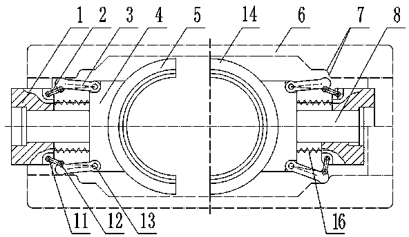
[0033] Such as figure 1 Shown is the embodiment 1 of the hub bulging device in the present invention. The hub bulging device includes a flap closing module and a mold locking mechanism, wherein the flap closing module is a laterally split-type molding used when the hub is bulging. Die structure, the clamping mechanism includes a constraint frame 6, and two clamping constraint mechanisms connected to the flap closing module, the clamping constraint mechanisms are arranged on the opposite sides of the flap closing module, and each clamping constraint mechanism includes a fixer 4 and connector 1. When in use, the fixer 4 is used to fix the corresponding valve closure module. The connector 1 is connected to the piston rod of the hydraulic cylinder that provides the mold clamping force. The piston rod can drive the connector 1 when it moves. sports. figure 1 ...


PUM


Abstract

The invention relates to the technical field of metal plastic-processing, provides a wheel hub bulging device and a mold locking mechanism thereof, and solves the problem that in the prior art, the mold rigidity is low and the product precision is influenced because the mold closing force is small. The wheel hub bulging device comprises split modules and the mold locking mechanism, wherein the mold locking mechanism comprises a restraining frame and a mold-closing restraining mechanism; the mold-closing restraining mechanism is capable of pushing the split modules to move oppositely in the left and right direction, and comprises a fixer, a connector and connecting rod mechanisms; the connecting rod mechanisms are symmetric in the front and rear direction, and comprise swinging rods and connecting rods; bulges are arranged at the swinging ends of the swinging rods; sliding holes positioned on the outer sides of the swinging rods are formed in the restraining frame; springs are arrangedbet ween the fixer and the connector; when the connector is driven by a piston rod to perform mold closing motion, the fixer is pushed by the springs to move synchronously; after the mold closing motion is completed, the connector is driven by the piston rod to keep moving forward; the springs are compressed; the connecting rods and the swinging rods are enabled to swing outward; and the bulges are enabled to slide into the sliding holes and matched with the sliding holes to be propped against the fixer, so that the mold locking operation can be achieved.

Description

technical field [0001] The invention relates to the technical field of metal plastic processing, in particular to a hub bulging device and a mold locking mechanism thereof. Background technique [0002] At present, with the development of the national economy, the automobile industry is developing extremely rapidly, and the precision plastic forming technology of light alloy automobile wheel hub has become the development direction of automobile wheel hub forming technology. [0003] The authorized announcement number is CN102179665B, and the Chinese invention patent whose authorized announcement date is 2014.07.16 discloses a complete set of composite molds for the plastic forming of automobile wheels. The flap-type lower mold includes more than two concave mold segments and a lower punch arranged under the concave mold flaps. The center of the lower punch is slidably inserted with an ejector, and the upper mold includes a flap-type lower mold. Coordinated extrusion upper ...

Claims


Application Information

Patent Timeline
Patent Type & Authority Patents(China)
IPC IPC(8): B21D53/26B21D37/10B21D26/00
Inventor 杨茜杨永顺虞跨海陈拂晓郭俊卿
Owner 江苏宗颐新材料科技有限公司
Why Eureka
Try Eureka