Movable anti-theft charging pile system

A charging pile system and technology of charging piles, which are applied in electric vehicle charging technology, charging stations, electric vehicles, etc., can solve the problems of inconvenient replacement and maintenance of charging piles, insufficient anti-theft performance, inconvenient use, etc., so as to improve the use safety, The effect of reducing the chance of theft

Active Publication Date: 2019-05-14
ANHUI NENGTONG NEW ENERGY TECH CO LTD
View PDF9 Cites 3 Cited by
  • Summary
  • Abstract
  • Description
  • Claims
  • Application Information

AI Technical Summary

Problems solved by technology

[0002] Most of the current charging piles are installed in car maintenance stations, residential areas, or parking lots. They are installed on both sides of the road and in unmanaged areas such as public parking lots. They are easy to be stolen. The lines and wires inside the charging piles become The stealing target of the thieves, the whole charging pile is easy to obtain, easy to move, and easy to damage has become the reason for the thieves to steal
Moreover, the current charging piles are basically fixed on the ground and are not easy to move, which brings some inconvenience to the replacement and maintenance of charging piles.
[0003] Chinese patent CN207416565U announces a charging pile for electric vehicles with anti-theft function, including a charging pile device. The charging pile device includes a casing, a display device, a charging gun, an IC card identification module and a main control module, and also includes an anti-theft device, a driving device and Anti-fool device; the anti-theft device includes an anti-theft box, guide rails are provided on both sides of the anti-theft box, racks are fixed on the lower surface, support blocks are fixed on the left and right sides of the inner surface of the shell, and the support blocks are provided with guide rail grooves. Sliding sleeve; the driving device includes gears, couplings and motors, the gears are meshed with the rack, and the gears and the motor are fixedly connected through the coupling; the foolproof device includes a pressure sensor, the pressure sensor is electrically connected to the main control module, and the motor It is electrically connected with the main control module, and the pressure sensor is fixedly arranged at the bottom of the inner surface of the anti-theft box. The utility model is simple in structure, easy to use, and has outstanding practical effects. Although this structure improves the safety of the utility model, the anti-theft performance is still not enough. Moreover, the charging pile cannot move freely, which is inconvenient to use

Method used


Image

  • Movable anti-theft charging pile system
  • Movable anti-theft charging pile system
  • Movable anti-theft charging pile system

Examples


Embodiment 1

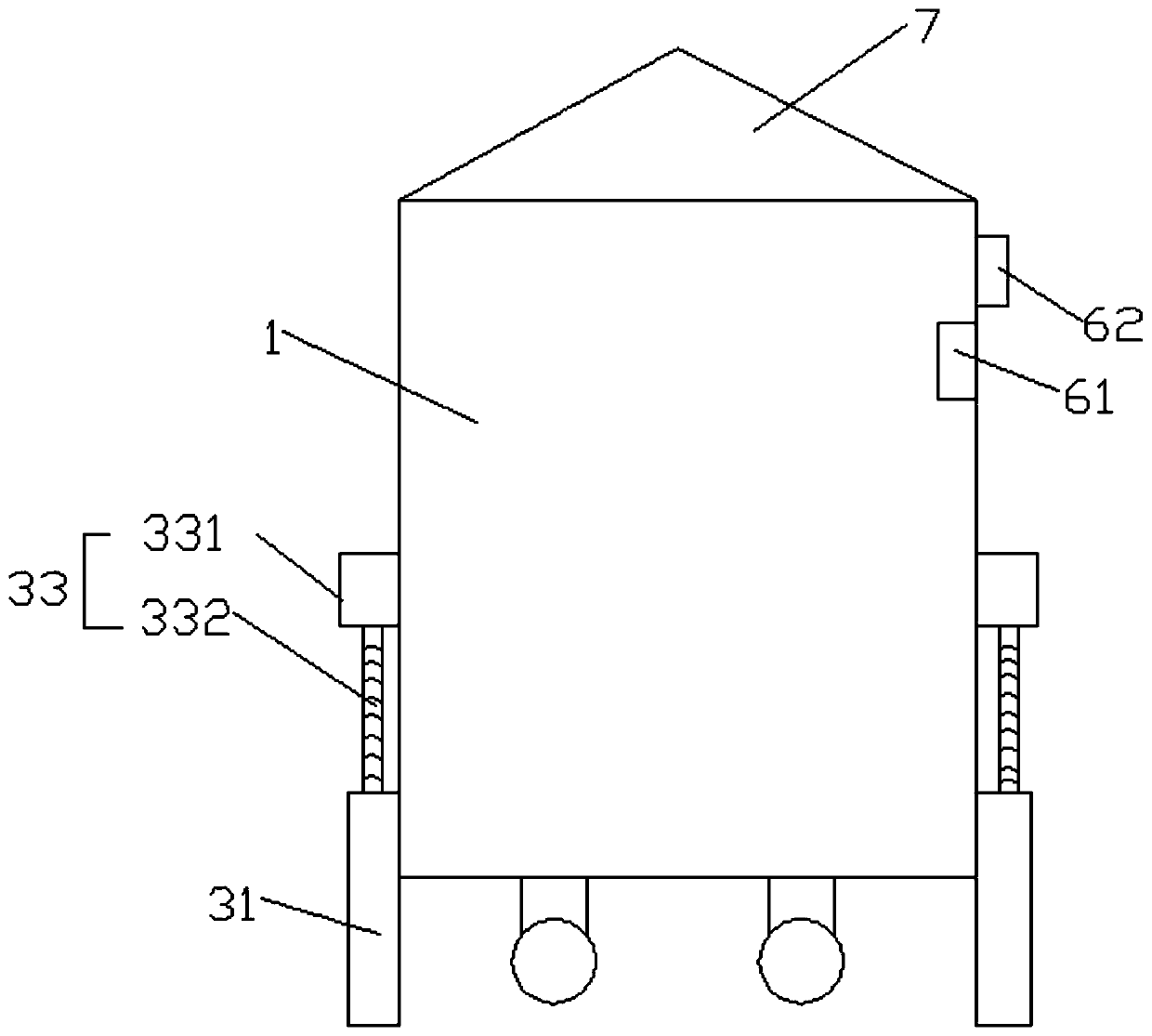
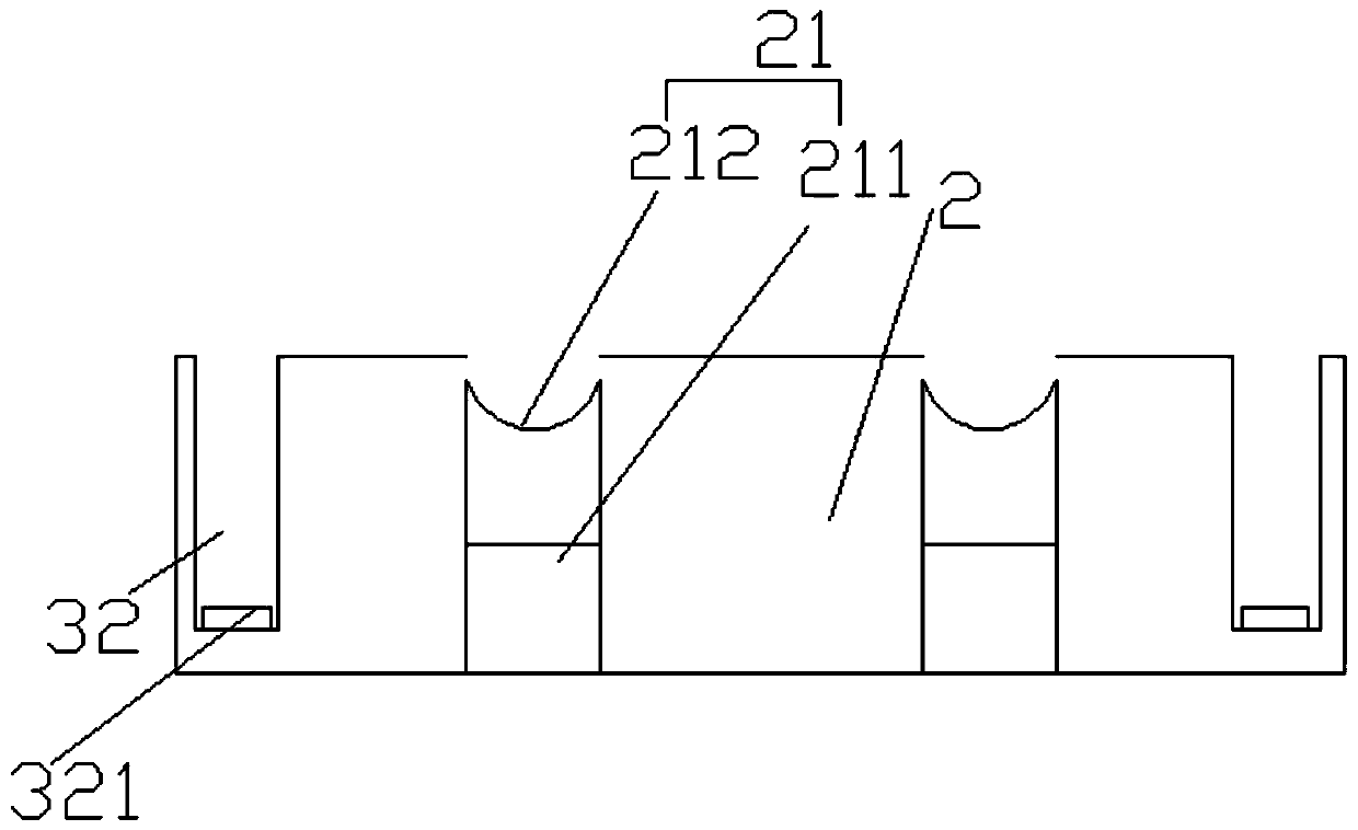
[0045] Such as image 3 , Figure 4 and Figure 5 As shown, this embodiment is an implementation of the anti-theft clamping device 3. The anti-theft clamping device 3 includes a clamping plate 31 and a first clamping groove 32. The clamping plate 31 is arranged on the side wall of the charging pile body 1. A driving device 33 is provided on the upper part of the connecting plate 31, the first engaging groove 32 is arranged in the installation base 1, and the bottom of the first engaging groove 32 is provided with a first pressure sensor 321. Under the operation of the driving device 33, the engaging plate 31 The second movable cover plate 322 is arranged above the first locking slot 32 to achieve engagement or separation from the first locking slot 32 .

[0046] The driving device 33 includes a first driving motor 331 and a driving shaft 332. The first driving motor 331 is arranged on the side wall of the charging pile body 1. The driving shaft 332 is arranged on the output ...

Embodiment 2

[0051] Such as Figure 6 , Figure 8 , Figure 9 and Figure 10 As shown, this embodiment is another embodiment of the anti-theft clamping device 3. The anti-theft clamping device 3 includes a clamping block sliding device 34 and a second clamping groove 35, and the second clamping groove 35 is provided inside the installation base 2 The wall, the bottom of the charging pile body 1 is provided with a hidden cavity 12, and the block sliding device 34 is arranged in the hidden cavity 12. The block sliding device 34 includes a sliding rod 341, a mounting block 342, a connecting rod 343 and a blocking block 344, and the mounting block 342 Set on the sliding rod 341, one end of the connecting rod 343 is set on the installation block 342, and one end is installed with a block 344. The side wall of the charging pile body 1 is provided with a second driving motor 36, and one end of the sliding rod 341 is connected to the second driving motor 36 , one end is connected to the other s...


PUM


Abstract

The invention discloses a movable anti-theft charging pile system, and relates to the field of charging piles. The movable anti-theft charging pile system comprises a charging pile body and a mountingbase, the charging pile body is arranged on the upper part of the mounting base, and the charging pile body is connected with the mounting base through an anti-theft clamping device; position indicators are arranged in the charging pile body and the mounting base correspondingly; supporting frames are arranged at the bottom of the charging pile body, and moving wheels are arranged on the supporting frames; wheel fixing devices are arranged in the mounting base and comprise telescopic seats and fixing grooves formed in the telescopic seats; the fixing grooves are each in a circular arc shape and adapt to the moving wheels in size; and a first movable cover plate is arranged at the tops of the wheel fixing devices, and automatic telescopic rods are adopted as the telescopic seats. Accordingto the movable anti-theft charging pile system, the charging pile body and the mounting base can be moved to be separated, meanwhile, the charging pile body and the mounting base are provided with aself-locking clamping structure, the intelligent anti-theft effect is achieved, and the using safety of the charging pile is improved.

Description

technical field [0001] The invention belongs to the field of charging posts, and in particular relates to a movable anti-theft charging post system. Background technique [0002] Most of the current charging piles are installed in car maintenance stations, residential areas, or parking lots. They are installed on both sides of the road and in unmanaged areas such as public parking lots. They are easy to be stolen. The lines and wires inside the charging piles become The stealing target of the thieves, the whole charging pile is easy to obtain, easy to move, and easy to damage has become the reason for the thieves to steal. Moreover, the current charging piles are basically fixed on the ground and are not easy to move, which brings some inconvenience to the replacement and maintenance of the charging piles. [0003] Chinese patent CN207416565U announces a charging pile for electric vehicles with anti-theft function, including a charging pile device. The charging pile device ...

Claims


Application Information

Patent Timeline
Patent Type & Authority Applications(China)
IPC IPC(8): B60L53/31
CPCY02T10/7072Y02T10/70Y02T90/12
Inventor 陶旭何仕玉张文飞
Owner ANHUI NENGTONG NEW ENERGY TECH CO LTD
Why Eureka
Try Eureka