Semi-automatic spiral type lifting device

A lifting device and spiral technology, applied in the field of lifting columns, can solve the problems of waste of resources, less lifting work, and high cost, and achieve the effects of convenient traffic management, expansion of lifting modes, and reduction of use costs.

Active Publication Date: 2019-05-17
苏州希恒建筑工程有限公司
View PDF7 Cites 0 Cited by
  • Summary
  • Abstract
  • Description
  • Claims
  • Application Information

AI Technical Summary

Problems solved by technology

Semi-automatic locking type, inconvenient to install, shaking after installation is not firm
Although fully automatic lifting columns have multiple lifting modes in operation, the cost is too high. For places where vehicles do not pass frequently, fully automatic lifting columns rarely perform lifting work, resulting in waste of resources.

Method used


Image

  • Semi-automatic spiral type lifting device
  • Semi-automatic spiral type lifting device
  • Semi-automatic spiral type lifting device

Examples


Embodiment Construction

[0030] The following will clearly and completely describe the technical solutions in the embodiments of the present invention with reference to the accompanying drawings in the embodiments of the present invention. Obviously, the described embodiments are only some, not all, embodiments of the present invention. Based on the embodiments of the present invention, all other embodiments obtained by persons of ordinary skill in the art without making creative efforts belong to the protection scope of the present invention.

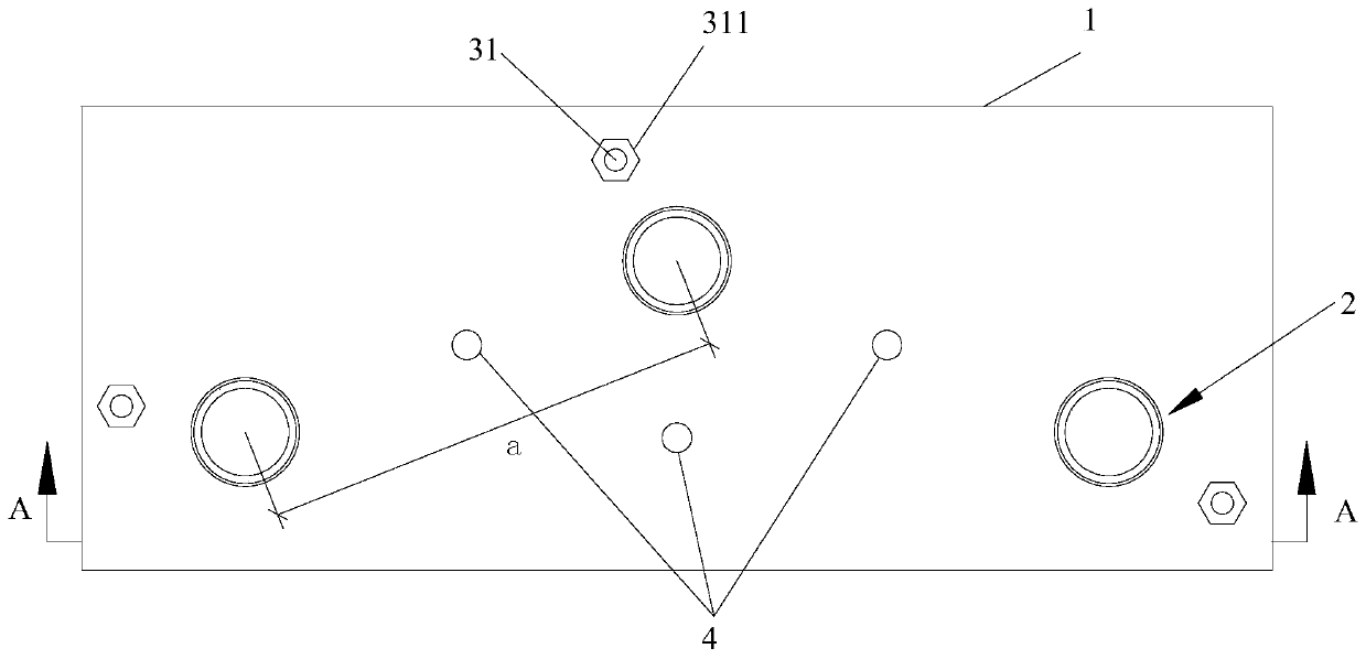
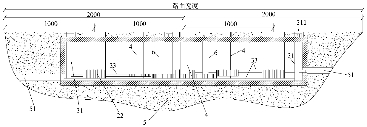
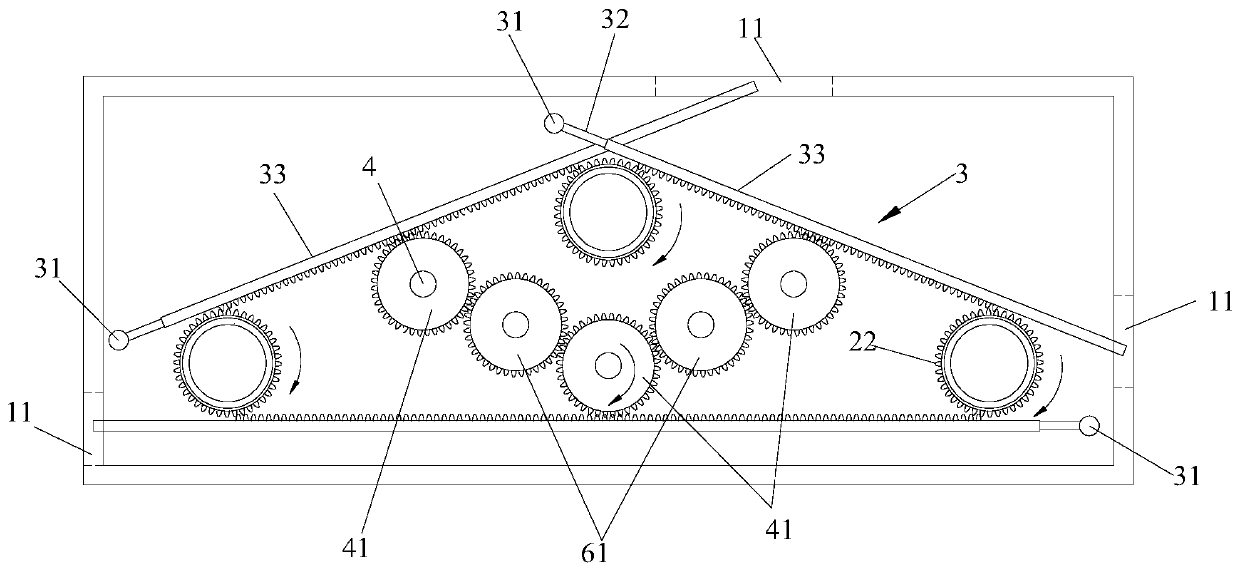
[0031] Such as Figure 1 to Figure 11 As shown, a semi-automatic spiral lifting device includes a cuboid installation box 1 built in the concrete road layer 5, and three lifting bodies 2 in a triangular distribution are arranged in the installation box 1, and the three lifting bodies 2 are installed in the installation box. 1. The line connecting the centers of the projections at the bottom forms an isosceles obtuse triangle. Three driving arms 3 for driving t...


PUM


Abstract

The invention discloses a semi-automatic spiral type lifting device. The semi-automatic spiral type lifting device comprises a mounting box arranged in a concrete road layer; three lifting bodies arearranged in the mounting box; three driving arms are arranged in the mounting box; three first rotating shafts are arranged in the middle of the adjacent two lifting bodies; a driving gear is fixedlyarranged on each first rotating shaft; and the tooth number of the driving gear is as same as that of a driven gear. The parts are centralized together through the mounting box and the mounting box isembedded in the concrete road layer, so that the unstable problem in dispersed mounting is avoided; meanwhile, the lifting bodies adopt a triangular distribution mode, so on one hand, vehicle passageis obstructed, and on the other hand, through cooperation with the three driving arms, synchronous lifting of three lifting columns, synchronous lifting of two lifting columns and single lifting of single lifting column are realized and the lifting mode of the lifting columns is expanded.

Description

technical field [0001] The invention relates to the technical field of lifting columns, in particular to a semi-automatic spiral lifting device. Background technique [0002] With the improvement of urban management, many places have adopted the form of lifting bollards to control vehicle traffic, making lifting bollards widely used in the passageway entrances and exits of infrequently passing vehicles (such as: fire exits, parks, pedestrian streets, etc.). The lifting columns on the existing market are mainly semi-automatic locking type or fully automatic remote control type. But there are more or less certain problems. The semi-automatic lock type is inconvenient to install, and the shaking after installation is not firm. Although fully automatic lifting columns have multiple lifting modes in operation, the cost is too high. For places where vehicles do not pass frequently, fully automatic lifting columns rarely perform lifting work, resulting in waste of resources. Co...

Claims


Application Information

Patent Timeline
Patent Type & Authority Applications(China)
IPC IPC(8): E01F13/04
Inventor 周江华
Owner 苏州希恒建筑工程有限公司
Why Eureka
Try Eureka