Eureka AIR delivers breakthrough ideas for toughest innovation challenges, trusted by R&D personnel around the world.

Hydroelectric generating device for underwater unmanned aircraft

A technology of hydroelectric power generation device and unmanned aerial vehicle, which is applied in the direction of hydropower generation, machine/engine, propulsion device engine, etc., and can solve the problem of difficult to realize the organic unity of the system, complex connection, and influence on the power generation effect of the vertical axis ocean current energy generation device underwater Aircraft operational performance and safety issues

Active Publication Date: 2019-05-17
HARBIN ENG UNIV
View PDF11 Cites 1 Cited by
  • Summary
  • Abstract
  • Description
  • Claims
  • Application Information

AI Technical Summary

Problems solved by technology

This device divides the aircraft into three sections, making the connection between the front section, the middle section and the rear section more complicated, which will affect the original internal structure of the aircraft, making it difficult to achieve an organic unity of the system
Each vertical axis ocean current power generation device has a set of hydraulic system consisting of hydraulic oil tank, plunger pump, hydraulic pipeline and rotary joint. The hydraulic system not only occupies a lot of space inside the aircraft, but once the hydraulic system fails, it will affect the The power generation effect of vertical axis ocean current power generation device and the operating performance and safety of underwater vehicles

Method used


Image

  • Hydroelectric generating device for underwater unmanned aircraft
  • Hydroelectric generating device for underwater unmanned aircraft
  • Hydroelectric generating device for underwater unmanned aircraft

Examples


specific Embodiment approach 1

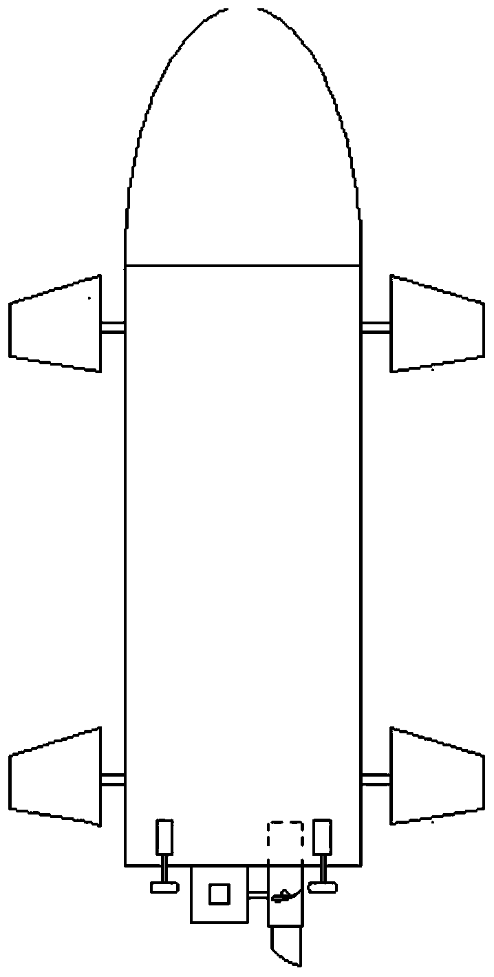
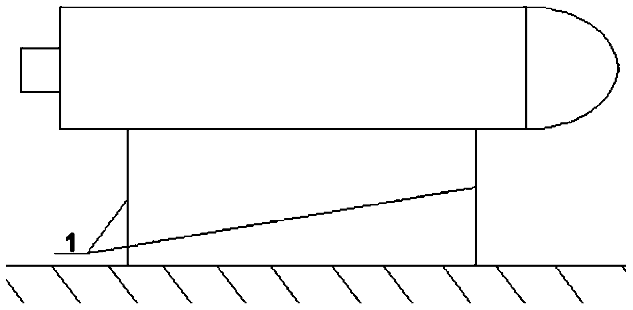
[0018] Specific implementation mode 1: see figure 1 , figure 2 , image 3 , Figure 4 and Figure 5 .

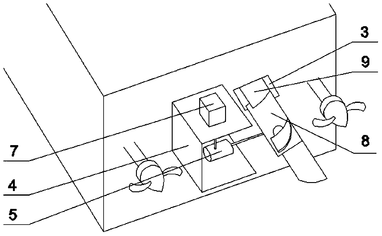
[0019] When the underwater unmanned vehicle is sailing, the overall power generation device is installed on the left side of the middle of the two propellers outside the tail end of the underwater unmanned vehicle. 2. Extend the tail end of the aircraft through the push rod and fix it with the rear side of the cabin body 4 of the permanent magnet generator 5. The cabin body 4 is close to the outside of the tail end of the aircraft. The blades 9 of the water turbine 8 are stored in the blade recovery cabin 3, such as image 3 and 4 shown.

[0020] When the underwater unmanned vehicle needs to be charged, the combination figure 2 , 3 , 4 and 5. First, the underwater unmanned vehicle figure 2 The double anchor chain method is fixed, and then the push rod of the push rod motor 2 is stretched out from the tail end of the aircraft to push the whole power generation de...

specific Embodiment approach 2

[0022] Specific implementation mode 2: Participate in Figure 6 .

[0023] The overall power generation device of the underwater unmanned vehicle is installed in the middle of the propeller at the tail end of the aircraft, the blade recovery cabin 3 is on the upper side of the power generation device, the cabin body 4 of the permanent magnet generator 5 is fixed to the tail end of the aircraft, and the stepping motor cabin 7 is fixed on the left side of cabin body 4, as Figure 6 shown. The operation of the power generation device is slightly different from the specific mode 1, and it does not need to control the expansion and contraction of the whole power generation device. When charging the aircraft, it is only necessary to make the stepper motor in the stepper motor cabin 7 drive the permanent magnet generator 5 from upward to downward. Just rotate the front 90°, and the rest of the process is the same.


PUM


Abstract

The invention belongs to the field of underwater unmanned sailing, and particularly relates to a hydroelectric generating device for an underwater unmanned aircraft. A hydroelectric generating deviceis installed at the tail part of the underwater unmanned aircraft to charge the underwater unmanned aircraft, ocean current can drive blades of the hydroelectric generating device to rotate so as to drive an electric generator to generate electric energy and store the electric energy in the storage battery, the working requirements of the aircraft are completely met, and the purpose of permanent cruising is achieved. The underwater unmanned aircraft can meet power required by ocean detection through the added hydroelectric generating device; when the underwater unmanned aircraft detects at a fixed point, the underwater unmanned aircraft can also be charged by utilizing the hydroelectric generating device; the hydroelectric generating device is arranged at the tail part of the aircraft, andoccupies a small space in the aircraft; and the hydroelectric generating device can contract the blades to be close to the aircraft, so that the hydroelectric generating device does not influence sailing of the underwater unmanned aircraft and navigational speed of the underwater unmanned aircraft.

Description

technical field [0001] The invention belongs to the field of underwater unmanned navigation, in particular to a hydroelectric power generation device for an underwater unmanned vehicle. Background technique [0002] The ocean accounts for 71% of the earth's surface, with a vast area and rich marine resources, but the degree of development and utilization is still very low. Therefore, it is of great significance to explore marine resources. In order to understand the distribution of marine resources, countries have successively conducted research on underwater unmanned aerial vehicles since the late 1950s, and underwater unmanned aerial vehicles can not only detect marine resources, but also be used for military activities, such as intelligence collection, communication relay and mine detection etc. Due to the small size and limited capacity of traditional underwater unmanned vehicles, the energy of the power supply system is limited, so the battery life is not strong, and i...

Claims


Application Information

Patent Timeline
Patent Type & Authority Applications(China)
IPC IPC(8): F03B13/00F03B11/00B63H21/17
CPCY02E10/20
Inventor 程鹏史超李睿烨兰海李伟力王晓超成倩梁宁李攀龙
Owner HARBIN ENG UNIV
Why Eureka
Eureka Blog
Learn More