A hydroelectric power generation device for underwater unmanned vehicles
A technology of hydroelectric power generation device and unmanned aerial vehicle, which is applied in the directions of hydroelectric power generation, machine/engine, propulsion device engine, etc., can solve the problem of affecting the internal structure of the aircraft and affecting the power generation effect of the vertical axis ocean current energy power generation device. The operation of the underwater vehicle Problems such as performance and security, and difficulty in realizing the organic unity of the system
- Summary
- Abstract
- Description
- Claims
- Application Information
AI Technical Summary
Problems solved by technology
Method used
Image
Examples
specific Embodiment approach 1
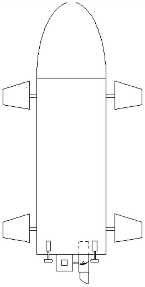
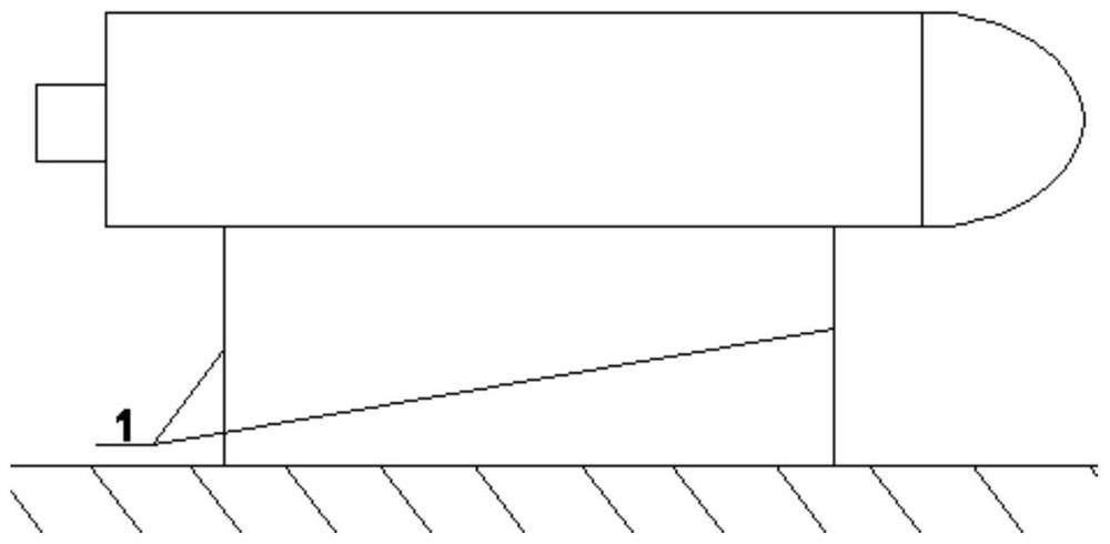
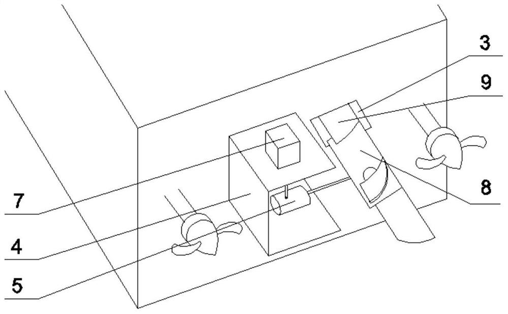
[0018] Specific implementation mode 1: see figure 1 , figure 2 , image 3 , Figure 4 and Figure 5 .
[0019] When the underwater unmanned vehicle is sailing, the overall power generation device is installed on the left side of the middle of the two propellers outside the tail end of the underwater unmanned vehicle. 2. Extend the tail end of the aircraft through the push rod and fix it with the rear side of the cabin body 4 of the permanent magnet generator 5. The cabin body 4 is close to the outside of the tail end of the aircraft. The blades 9 of the water turbine 8 are stored in the blade recovery cabin 3, such as image 3 and 4 shown.
[0020] When the underwater unmanned vehicle needs to be charged, the combination figure 2 , 3 , 4 and 5. First, the underwater unmanned vehicle figure 2 The double anchor chain method is fixed, and then the push rod of the push rod motor 2 is stretched out from the tail end of the aircraft to push the whole power generation de...
specific Embodiment approach 2
[0022] Specific implementation mode 2: Participate in Image 6 .
[0023] The overall power generation device of the underwater unmanned vehicle is installed in the middle of the propeller at the tail end of the aircraft, the blade recovery cabin 3 is on the upper side of the power generation device, the cabin body 4 of the permanent magnet generator 5 is fixed to the tail end of the aircraft, and the stepping motor cabin 7 is fixed on the left side of cabin body 4, as Image 6 shown. The operation of the power generation device is slightly different from the specific mode 1. It does not need to control the expansion and contraction of the whole power generation device. When charging the aircraft, it only needs to make the stepping motor in the stepping motor cabin 7 drive the permanent magnet generator 5 from upward to downward. Just rotate the front 90°, and the rest of the process is the same.
PUM
 Abstract
Description
Claims
Application Information
 - R&D
- Intellectual Property
- Life Sciences
- Materials
- Tech Scout
- Unparalleled Data Quality
- Higher Quality Content
- 60% Fewer Hallucinations
Browse by: Latest US Patents, China's latest patents, Technical Efficacy Thesaurus, Application Domain, Technology Topic, Popular Technical Reports.
© 2025 PatSnap. All rights reserved.Legal|Privacy policy|Modern Slavery Act Transparency Statement|Sitemap|About US| Contact US: help@patsnap.com


