A charging system for underwater unmanned vehicles with permanent endurance

An unmanned vehicle and capability technology, which is applied in the directions of underwater ships, ocean energy power generation, underwater operation equipment, etc. Problems such as performance and security, and difficulty in realizing the organic unity of the system

Active Publication Date: 2020-12-04
HARBIN ENG UNIV
View PDF5 Cites 0 Cited by
  • Summary
  • Abstract
  • Description
  • Claims
  • Application Information

AI Technical Summary

Problems solved by technology

This device divides the aircraft into three sections, making the connection between the front section, the middle section and the rear section more complicated, which will affect the original internal structure of the aircraft, making it difficult to achieve an organic unity of the system
Each vertical axis ocean current power generation device has a set of hydraulic system consisting of hydraulic oil tank, plunger pump, hydraulic pipeline and rotary joint. The hydraulic system not only occupies a lot of space inside the aircraft, but once the hydraulic system fails, it will affect the The power generation effect of vertical axis ocean current power generation device and the operating performance and safety of underwater vehicles

Method used


Image

  • A charging system for underwater unmanned vehicles with permanent endurance
  • A charging system for underwater unmanned vehicles with permanent endurance
  • A charging system for underwater unmanned vehicles with permanent endurance

Examples


specific Embodiment approach 1

[0026] Specific implementation mode 1: see figure 1 , figure 2 , image 3 , Figure 4 , Figure 5 , Figure 6 , Figure 7 , Figure 8 , Figure 9 , Figure 10 and Figure 11 .

[0027] The present invention is structured as follows:

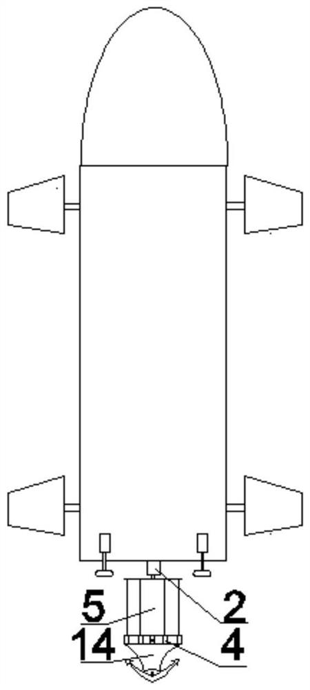
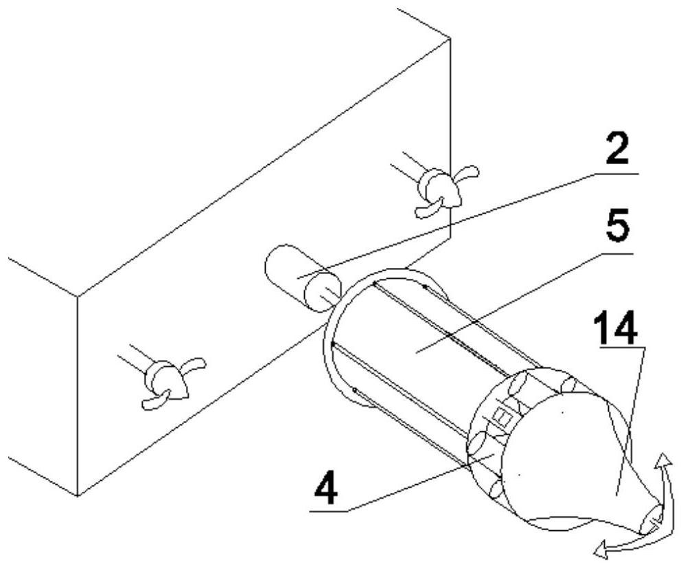
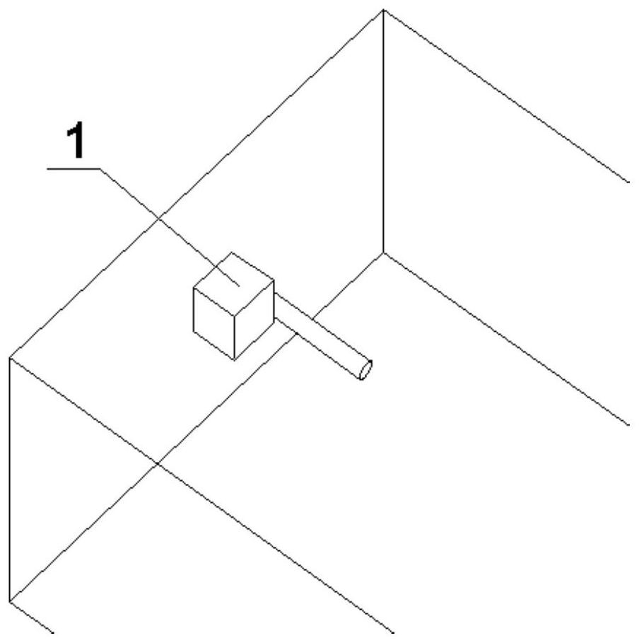
[0028] A charging system scheme 1 suitable for underwater unmanned vehicles with permanent endurance, such as figure 1 , 2 Shown in and 3, comprise push rod motor 1, permanent magnet generator cabin 2, stepper motor, vertical axis type water turbine 5 and anchoring equipment. The overall power generation device of the underwater unmanned vehicle is installed on the outside of the tail of the underwater unmanned vehicle, such as figure 1 and 2 As shown, the push rod motor 1 is installed on the inner side of the tail end of the underwater unmanned vehicle, as shown in image 3 shown. The push rod motor 1 is fixed to the bottom of the permanent magnet generator cabin 2 through the push rod protruding from the tail end of the aircraf...

specific Embodiment approach 2

[0033] Specific implementation mode 2: Participate in Figure 8 and Figure 12 .

[0034] Power generation devices for underwater unmanned vehicles such as Figure 8 As shown, it is the remaining part of the overall power generation device in Embodiment 1 except the mooring equipment. When the underwater unmanned vehicle needs to be charged, the underwater unmanned vehicle uses Figure 12 The method is anchored and fixed, and when the underwater vehicle is sailing and charging, the implementation process of the power generation device is consistent with the specific embodiment 1.


PUM


Abstract

The invention belongs to the field of unmanned underwater vehicles and in particular relates to a charging system suitable for an unmanned underwater vehicle with permanent endurance. According to thecharging system suitable for the unmanned underwater vehicle with permanent endurance, the unmanned underwater vehicle is charged by mounting a hydro-electric power generating device at the tail partof the unmanned underwater vehicle; an ocean current can drive blades of the hydro-electric power generating device to rotate so as to drive a power generator to generate electric energy and store the electric energy in a storage battery; and therefore, a working demand of the vehicle is completely satisfied, and a permanent endurance purpose is achieved. The unmanned underwater vehicle can satisfy electric power needed by ocean detection by using the mounted hydro-electric power generating device; when the unmanned underwater vehicle performs fixed-point detection, the unmanned underwater vehicle can also be charged by using the hydro-electric power generating device; the hydro-electric power generating device is mounted at the tail part of the vehicle and occupies very small internal space of the vehicle; the blades of the hydro-electric power generating device can retract to be close to the vehicle so that the hydro-electric power generating device does not affect the sailing and sailing speed of the unmanned underwater vehicle.

Description

technical field [0001] The invention belongs to the field of underwater unmanned navigation, in particular to a charging system suitable for underwater unmanned vehicles with permanent endurance. Background technique [0002] The ocean accounts for 71% of the earth's surface, with a vast area and rich marine resources, but the degree of development and utilization is still very low. Therefore, it is of great significance to explore marine resources. In order to understand the distribution of marine resources, countries have successively conducted research on underwater unmanned aerial vehicles since the late 1950s, and underwater unmanned aerial vehicles can not only detect marine resources, but also be used for military activities, such as intelligence collection, communication relay and mine detection etc. Due to the small size and limited capacity of traditional underwater unmanned vehicles, the energy of the power supply system is limited, so the battery life is not str...

Claims


Application Information

Patent Timeline
Patent Type & Authority Patents(China)
IPC IPC(8): B63G8/00F03B13/22
CPCB63G8/001B63G2008/002F03B13/22Y02E10/30
Inventor 程鹏史超李睿烨兰海李伟力王晓超成倩梁宁李攀龙
Owner HARBIN ENG UNIV
Why Eureka
Try Eureka