Finger rehabilitation robot with adduction and abduction functions

A rehabilitation robot and finger technology, applied in the direction of manipulators, manufacturing tools, passive exercise equipment, etc., can solve the problems of single degree of freedom, poor flexibility, etc., achieve low product cost, reduce production cost, and avoid secondary damage.

Inactive Publication Date: 2019-05-21
YANSHAN UNIV
10 Cites 7 Cited by

AI-Extracted Technical Summary

Problems solved by technology

[0011] Aiming at the defects of poor flexibility and single degree of freedom of the finger rehabilitation robot in the prior art, the present invention provides a robot with four-finger adduction/abduction that can perform multiple degree...

Abstract

The invention discloses a finger rehabilitation robot with adduction and abduction functions, and relates to the technical field of rehabilitation medical equipment. The robot comprises a rack, a four-finger flexion/stretching exercise assembly, a four-finger adduction/abduction exercise assembly, a thumb exercise assembly and a forearm supporting assembly; the four-finger flexion/stretching exercise assembly comprises a linear sliding table bottom plate, a flexion and stretching motor and a lead screw nut mechanism; a finger motion track restraining plate is arranged on the upper portion of alead screw of the lead screw nut mechanism; the four-finger adduction/abduction exercise assembly comprises an adduction and abduction motor, a swinging driving plate, a short connecting rod and a long connecting rod; the thumb exercise assembly comprises a thumb exercise motor, a thumb exercise driving belt wheel, a thumb exercise synchronous belt, a thumb exercise driven belt wheel and a thumbsleeve component. The robot can achieve four-finger flexion/stretching exercise and four-finger adduction/abduction exercise, is good in mechanism flexibility, cannot cause secondary injury, and is good in rehabilitation effect and high in cost performance.

Application Domain

Technology Topic

Image

  • Finger rehabilitation robot with adduction and abduction functions
  • Finger rehabilitation robot with adduction and abduction functions
  • Finger rehabilitation robot with adduction and abduction functions

Examples

  • Experimental program(1)

Example Embodiment

[0049] Embodiment one:
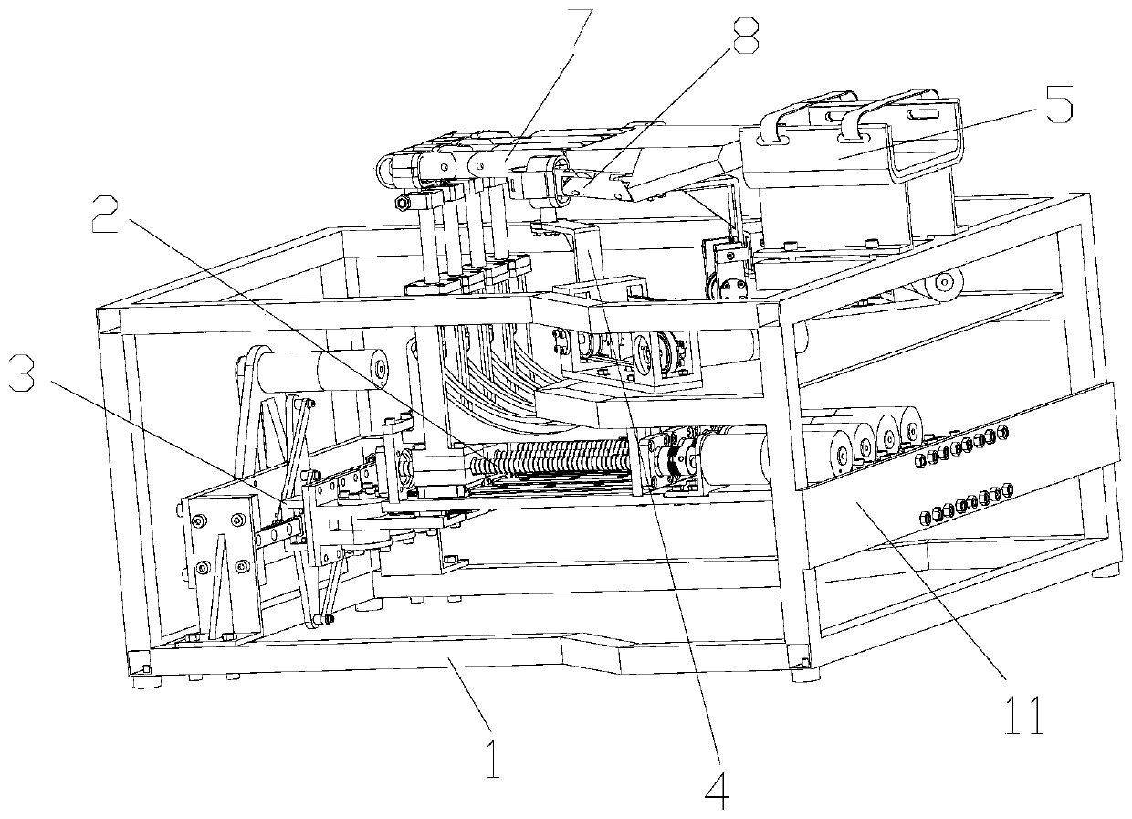
[0050] like figure 1 As shown, this embodiment provides a finger rehabilitation robot with adduction and abduction functions, including a frame 1, four four-finger flexion/extension movement assemblies 2, four-finger adduction/abduction movement assemblies 3 and two thumbs Motion assembly 4; two sides of the four four-finger flexion/extension motion assemblies 2 are respectively provided with a thumb motion assembly 4.
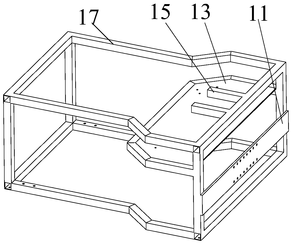
[0051] like Figure 1-14 As shown, the frame 1 includes a frame body 17, a front side plate 12, a rear side plate 11 and a thumb movement assembly mounting frame 13; the front side plate 12 is arranged on the front of the frame body 17, and the rear side plate 11 is arranged on the machine The rear portion of the frame body 17, the thumb motion assembly mounting frame 13 is arranged on the upper middle part in the frame body 17; one end of the four-finger flexion/extension motion assembly 2 is arranged on the rear side plate 11, and the four-finger adduction/extension motion assembly 3 is arranged on the front side plate 12, the thumb movement assembly 4 is arranged on the thumb movement assembly mounting frame 13, and the other end of the four-finger flexion/extension movement assembly 2 is movably connected to the four-finger adduction/abduction movement assembly 3; each One end of the four-finger flexion/extension movement assembly 2 is movably connected with the frame 1, and the other end of each four-finger flexion/extension movement assembly 2 is movably connected with a four-finger adduction/abduction movement assembly 3.
[0052] The four-finger flexion/stretch movement assembly 2 includes a linear slide base plate 22, a finger cover assembly 26, a finger motion trajectory constraint plate 28 and a transmission mechanism; Fixedly arranged on the bottom plate 22 of the linear slide table, the transmission mechanism is arranged at the rear part of the bottom plate 22 of the linear slide table, and the transmission mechanism is connected with the transmission between the finger cover assembly 26, and the finger movement trajectory restriction plate 28 is used to restrict the movement of the finger cover assembly 26. motion track.
[0053] Four refers to adduction/abduction movement assembly 3 and comprises retraction motor 31, swing dial 34, four four fingers retraction slider assembly 37, four connecting rods and four fingers retraction slide rail 38; Retraction motor 31 and Swing dial 34 power connection, four-finger retractable slide rail 38 is connected with frame 1, four four-finger retractable slide block assemblies 37 are movably arranged on four-finger retractable slide rail 38, and one end of four connecting rods is linear Set on the swing dial 34, the other ends of the four connecting rods are respectively connected to a four-finger stretching slider assembly 37, and each four-finger stretching slider assembly 37 is flexibly connected to a four-finger flexion/extension movement assembly 2 respectively .
[0054] A passive slide assembly is arranged between the four-finger flexion/stretch movement assembly 2 and the four-finger adduction/abduction movement assembly 3, and the passive slide assembly includes a passive slide platform bottom plate 39, a passive slide block 310 and a passive guide rail 311; the passive slide block 310 Fixedly arranged on the bottom plate 39 of the passive slide table, the passive guide rail 311 is flexibly connected with the passive slider 310; The stretching exercise assembly 2 is fixedly connected.
[0055] Thumb motion assembly 4 comprises base plate 47, thumb motion motor 41, thumb motion driving pulley 42, thumb motion driven pulley 43, thumb motion timing belt 44, thumb slider assembly 45 and thumb cover assembly 46; base plate 47 is installed with The frame 1 is connected, the thumb motion driving pulley 42 and the thumb motion driven pulley 43 are all rotatably arranged on the installation base plate 47, and the thumb motion timing belt 44 is arranged on the thumb motion driving pulley 42 and the thumb motion driven pulley 43 Between, the thumb slider assembly 45 is arranged on the thumb movement synchronous belt 44 , and the thumb cover assembly 46 is arranged on the thumb slider assembly 45 .
[0056] The thumb cover assembly 46 includes a connecting frame and a thumb cover 462 , the thumb cover 462 is rotatably arranged at a higher end of the connecting frame, and the lower end of the connecting frame is connected with the thumb slider assembly 45 .
[0057] The finger cot assembly 26 includes a first mounting frame 27 and a finger cot 261. The first mounting frame 27 is movably arranged on the bottom plate 22 of the linear slide table, and the first mounting frame 27 is connected to the power transmission mechanism. The finger cot 261 is movably arranged on the first On the mounting frame 27 , the finger cot 261 is flexibly connected with the finger movement trajectory restriction plate 28 .
[0058] A connecting rod is arranged between the finger cover 261 and the first mounting frame 27, the higher end of the connecting rod is rotationally connected with the finger cover 261, and the lower end of the connecting rod moves through the first mounting frame 27 and is connected with the finger movement track restriction plate. 28 active connections.
[0059] The finger motion trajectory restriction plate 28 includes a main board fixedly arranged on the bottom plate 22 of the linear slide table, a track hole 281 is arranged on the main board, and the bottom end of the finger cover 261 is movably connected with the track hole 281 .
[0060] The transmission mechanism includes a curved motor 24 and a screw nut mechanism, the finger cot assembly 26 is connected with the screw nut mechanism, and the curved motor 24 is used to drive the screw nut mechanism to drive the finger cot assembly 26 to reciprocate along the linear slide base plate 22 .
[0061] The screw nut mechanism includes a screw mandrel, a square nut 2511 and a fixed block; the screw mandrel is arranged on the bottom plate 22 of the linear slide table, and one end of the screw mandrel is connected with the power of the curved motor 24; the square nut 2511 is sleeved on the screw mandrel, and the square nut The nut 2511 is matched with the screw rod; the fixed block is fixedly connected with the square nut 2511; the first installation frame 27 is fixedly connected with the fixed block, and the fixed block is slidably connected with the bottom plate 22 of the linear slide table.
[0062] It also includes a forearm support assembly 5, which is arranged on the frame 1 and located at the rear of the thumb movement assembly 4 for supporting the forearm.
[0063] In a more specific embodiment, four bearing seat assemblies 21 are arranged on the rear side plate 11 , and each bearing seat assembly 21 is rotatably connected to a bottom plate 22 of the linear slide table. The passive slide base plate 39 is rotatably connected with a passive slide base plate mounting frame 313, the passive slide base plate mounting frame 313 is fixedly connected with the four-finger retractable slider assembly 37, when the four-finger retractable slide block assembly 37 is retracted along the four fingers When the extension slide rail 38 slides, one end of the linear slide base plate 22 rotates around the bearing seat assembly 21, and the other end slides along the four-finger extension slide rail 38 with the four-finger extension slider assembly 37, and passes through the passive slider 310 and the passive guide rail. The relative sliding between 311 compensates the length change between the four-finger stretching slider assembly 37 and the bearing seat assembly 21.
[0064] Further, a controller is also included, and the controller is electrically connected with the flex motor 24, the flex motor 31 and the thumb motion motor 41 to control the operation of the flex motor 24, the flex motor 31 and the thumb motion motor 41 to realize Various movements of the patient's fingers.
[0065] Furthermore, an FSR pressure sensor 6 is respectively arranged in the finger cover 261 and the thumb cover 462. Specifically, the FSR pressure sensor 6 can be bonded to the finger cover 261 and the thumb cover 462 by glue bonding, and each The FSR pressure sensors 6 are all electrically connected to the controller, and the pressure of each finger is detected by the FSR pressure sensor 6, and the pressure applied by the patient's finger on the finger cuff is monitored in real time, to obtain the patient's movement intention, and to adjust the speed and direction of the movement of the finger end in real time .
[0066] When in use, the forearm is placed on the forearm support assembly 5, the four fingers 7 are respectively inserted into the finger sleeves 261 of a four-finger flexion/extension movement assembly 2, the thumb 8 is inserted into the thumb sleeve 462, and passed through the Velcro 53 Fix the forearm; under the drive of the bending motor 24, the first mounting frame 27 drives the finger cover 261 to move along the track hole 281, and the motion track of the four fingers is the same shape as the track hole 281; Next, the swing dial 34 rotates to drive the four connecting rods to make the four-finger stretching slider assembly 37 move along the four-finger stretching slide rail 38, so that the four fingers 7 complete the adduction/abduction movement; the thumb movement motor 41 drives The driving wheel rotates, so that the thumb motion synchronous belt 44 moves between the thumb motion driving pulley 42 and the thumb motion driven pulley 43, thereby driving the thumb slider assembly 45 to reciprocate. The slider assembly 45 is fixedly connected, therefore, the thumb sleeve 462 driven by the L-shaped connecting frame 461 can also perform reciprocating movement, so that the thumb 8 completes the flexion/extension movement.

PUM

no PUM

Description & Claims & Application Information

We can also present the details of the Description, Claims and Application information to help users get a comprehensive understanding of the technical details of the patent, such as background art, summary of invention, brief description of drawings, description of embodiments, and other original content. On the other hand, users can also determine the specific scope of protection of the technology through the list of claims; as well as understand the changes in the life cycle of the technology with the presentation of the patent timeline. Login to view more.

Similar technology patents

Wound protective support

PendingCN109907863AAvoid secondary damageEasy to change dressing and check woundNon-surgical orthopedic devicesBiomedical engineeringPlane parallel
Owner:严志发

Medical transport bed

Owner:HARBIN GONGYANG SCI & TECH CONSULTATION CO LTD

Classification and recommendation of technical efficacy words

  • Good training effect
  • Avoid secondary damage

Electronic focal-length-adjustable glasses

Owner:JIANGSU ESFINO INTELLIGENT TECH CO LTD

Control system and method of intelligent wheelchair

Owner:安徽常春藤智慧养老科技有限公司

Upper-limb rehabilitation device of half-exoskeleton

ActiveCN106420261AAvoid secondary damageImprove safety and efficacyChiropractic devicesInput/outputExoskeleton
Owner:SHANGHAI JIAO TONG UNIV

Cardiopulmonary cerebral resuscitation rescue device in emergency internal medicine

InactiveCN109288663ASave rescue timeAvoid secondary damageElectrotherapyHeart stimulationCushionCam
Owner:THE AFFILIATED HOSPITAL OF QINGDAO UNIV
Why Eureka
Try Eureka