Squatting pan with function of easy sewage discharge

A technology of squatting toilet and sewage outlet, applied in the field of squatting toilet, can solve the problems of not easy to flush the dirt, insufficient impulse force of the auxiliary flushing pipeline, etc., and achieve the effect of easy sewage drainage and strong impact force of water flow

Pending Publication Date: 2019-05-21
杜龙虎
View PDF0 Cites 0 Cited by
  • Summary
  • Abstract
  • Description
  • Claims
  • Application Information

AI Technical Summary

Problems solved by technology

Since the auxiliary flushing pipe is directly connected to the main flushing pipe, the water pressure of the auxiliary flushing pipe is not high, and the impulse force of the auxiliary flushing pipe is not enough
Dirt is not easy to wash off

Method used


Image

  • Squatting pan with function of easy sewage discharge
  • Squatting pan with function of easy sewage discharge
  • Squatting pan with function of easy sewage discharge

Examples


example 1

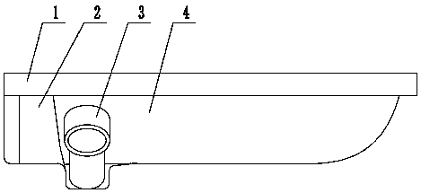
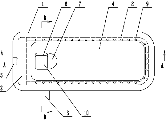
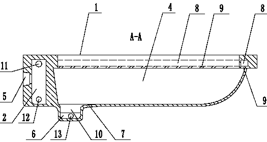
[0024] like Figure 1-7 The squatting pan that is easy to discharge sewage shown includes a panel 1, a urinal 4, a siphon 3, a main flushing pipeline and an auxiliary flushing pipeline 14, the urinal 4 is arranged on the lower side of the panel 1, and the rear end of the bottom of the urinal 4 is arranged There is a sewage outlet 10, the inlet of the siphon pipe 3 is directly connected to the sewage outlet 10, the outlet 13 of the auxiliary flushing pipeline is facing the inlet of the siphon pipe 3, and the back side of the urinal 4 is provided with a water storage chamber 2, and the water storage chamber 2 is provided with a water inlet 5 , the water inlet 5 is a tapered hole, the inside of the small end of the tapered hole is provided with a block, and the large end of the tapered hole is far away from the water storage chamber 2 relative to the small end.

[0025] Both sides of the upper part of the water storage chamber 2 are provided with an inlet 11 of a main flushing wa...

example 2

[0028] As shown in Fig. 8, the second example is to add a water tank 15 on the basis of the first example, the bottom of the water tank 15 communicates with the water inlet 5, and the water tank 15 is provided with a flush valve. Water tank 15 adopts the conventional water tank of squatting pan to get final product now.

[0029] Working principle: when flushing, water enters the water storage chamber 2 from the water inlet 5, and part of the water enters the main flushing pipeline, and is flushed out from the flushing port 9 to shower the inner wall of the urinal 4 and the sides of the urinal 4. The water flow obliquely flushes backward, so that the water flow can better flow to the sewage outlet 10 , and even if there is no flushing outlet 9 at the rear side of the urinal 2 , it can also be flushed. Another part of water flushes out the dirt that directly impacts the sewage outlet 10 from the auxiliary flushing water pipeline 14, and the dirt is washed into the siphon 3, so t...


PUM


Abstract

The invention discloses a squatting pan with a function of easy sewage discharge. The squatting pan comprises a panel, a urinal, a siphon, a main flushing pipeline and a secondary flushing pipeline, wherein the urinal is arranged at the lower side of the panel, the rear end of the bottom of the urinal is provided with a sewage discharge port, an inlet of the siphon is directly connected with the sewage discharge port, an outlet of the secondary flushing pipeline is directly opposite to the inlet of the siphon, the rear side of the urinal is provided with a water storage cavity, the water storage cavity is provided with a water inlet, the two ends of the main flushing pipeline are connected to the two sides of the upper portion of the water storage cavity respectively, and an inlet of the secondary flushing pipeline is connected to the lower portion of the water storage cavity. The squatting pan has the advantages that the water storage cavity is formed, the water flow of the main flushing pipeline is separated from the water flow of the secondary flushing pipeline through the water storage cavity, and the secondary flushing pipeline is connected to the bottom of the water storage cavity, so that the impact force of the water flow entering the secondary flushing pipeline is stronger, and the sewage discharge is easier.

Description

technical field [0001] The invention relates to a squatting toilet. Background technique [0002] Chinese Patent No. 201811173525X discloses a squatting pan with good sewage discharge effect. The squatting pan includes a panel, a urinal, a siphon, a main flushing pipeline and an auxiliary flushing pipeline. There is a sewage outlet at the end, and a water inlet is arranged on the panel. The water inlet and the auxiliary flushing pipeline are connected to the main flushing pipeline. The inlet of the siphon is directly connected to the sewage outlet, and the outlet of the siphon protrudes from the left or right side of the urinal. , the axis of the auxiliary flushing water pipeline and the axis of the siphon are in the same vertical plane, and the outlet of the auxiliary flushing water pipeline is facing the inlet of the siphon. Because the auxiliary flushing water pipeline is directly connected to the main flushing water pipeline, the water pressure of the auxiliary flushing...

Claims


Application Information

Patent Timeline
Patent Type & Authority Applications(China)
IPC IPC(8): E03D11/04E03D1/38
Inventor 杜龙虎
Owner 杜龙虎
Why Eureka
Try Eureka