
A horizontal straight-through tube double-cavity wave power generation device

A power generation device and a straight-through pipe technology, which is applied in the direction of ocean energy power generation, engine components, machines/engines, etc., can solve the problems of low energy conversion efficiency, high cost of ocean engineering, high construction cost, etc., and achieve improved capture width ratio and safety High reliability, low cost of production and use

Active Publication Date: 2021-03-23
GUANGZHOU INST OF ENERGY CONVERSION - CHINESE ACAD OF SCI
View PDF7 Cites 0 Cited by
  • Summary
  • Abstract
  • Description
  • Claims
  • Application Information

AI Technical Summary

Problems solved by technology

Floating static oscillating water column technology The floating body basically does not move, and the movement of the water column in the cavity is mainly generated by the direct action of waves, such as the "Giant Whale" device in Japan. The energy conversion efficiency of this type of technology is not high
[0004] The existing wave energy utilization technology has the disadvantages of high construction cost, high cost of marine engineering, and low safety

Method used


Image

  • A horizontal straight-through tube double-cavity wave power generation device
  • A horizontal straight-through tube double-cavity wave power generation device
  • A horizontal straight-through tube double-cavity wave power generation device

Examples


Embodiment

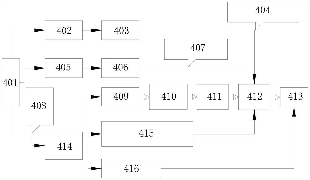
[0020] refer to figure 1 , the figure shows three prior art floating wave energy utilization technology classification diagrams; the reference signs in the figure represent respectively: 401, wave energy; 402, air kinetic energy; 403, air turbine; 404, oscillating water column technology ;405, seawater potential energy; 406, water turbine; 407, wave-surpassing technology; 408, oscillating float technology; 409, hydraulic cylinder; 410, high-voltage current regulator; 411, hydraulic motor; Structure mechanical energy; 415, mechanical structure (belt, gear transmission, etc.); 416, linear generator.

[0021] Floating motion oscillating water column technology mainly converts wave energy into the reciprocating motion of air chamber gas in the cavity of the floating body by the movement of the floating body, and then converts the aerodynamic energy into electrical energy through the air turbine and generator. This type of technology includes central tube technology and back bendin...


PUM


Abstract

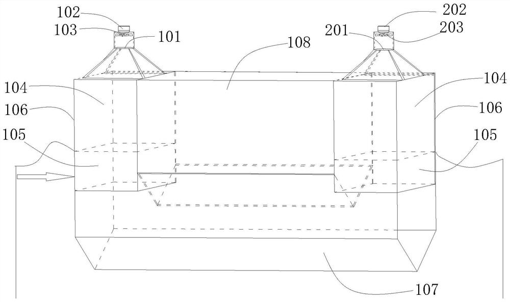
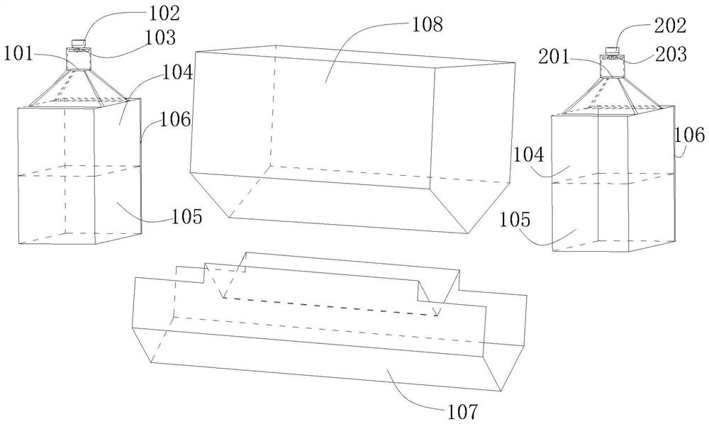
The invention discloses a horizontal straight-through pipe double-cavity wave force power generation device. The device comprises a buoyancy tank, a horizontal straight-through pipe, oscillating watercolumn power generation modules and mooring systems. The oscillating water column power generation modules include the first power generation module and the second power generation module. The firstpower generation module comprises a first cuboid cavity, a first air turbine and a first generator; and the second power generation module comprises a second cuboid cavity, a second air turbine and asecond generator. The buoyancy tank is arranged on the upper portion of the horizontal straight-through pipe and internally provided with power storage equipment. The lower portions of the first cuboid cavity and the second cuboid cavity are immersed into water. A first water column is formed on the lower portion of the first cuboid cavity, and a first air chamber is formed on the upper portion ofthe first cuboid cavity. A second water column is formed on the lower portion of the second cuboid cavity, and a second air chamber is formed on the upper portion of the second cuboid cavity. The mooring systems comprise anchor gears, anchor chains and anchors. The horizontal straight-through pipe double-cavity wave force power generation device is high in stability and wave resistance, the reflected wave energy is reduced, the conversion efficiency is improved, the ship towing oil consumption amount is reduced, and energy saving and environment friendliness are achieved.

Description

technical field [0001] The invention relates to the technical field of wave energy power generation, in particular to a horizontal straight-through tube double-cavity wave power generation device. Background technique [0002] Wave energy resources are abundant and have great potential for development and utilization. However, due to factors such as unstable wave energy, harsh marine environment, seawater corrosion, and marine organisms, the cost of developing and utilizing ocean wave energy is high. These costs are mainly reflected in the material cost of the device, construction cost, conversion mechanism cost, launch, transportation and recovery cost, anchoring cost, maintenance cost, etc. [0003] At present, there are many types of wave energy utilization technologies, and the floating wave energy utilization technology has become the mainstream of research because of its wide adaptability. Float technology such as figure 1 shown. Floating and oscillating buoy techn...

Claims


Application Information

Patent Timeline
Patent Type & Authority Patents(China)
IPC IPC(8): F03B13/14F03B13/24F03B13/18
CPCY02E10/30
Inventor 吴必军李猛张运秋
Owner GUANGZHOU INST OF ENERGY CONVERSION - CHINESE ACAD OF SCI
Learn More