Diaphragm structure and leak valve

A technology of diaphragm structure and air leakage valve, which is applied in the direction of valve device, engine components, mechanical equipment, etc., can solve the problems of poor flow capacity and poor reverse cut-off ability of air leakage valve, and achieve strong flow capacity and reverse Strong cut-off ability and high stability

Pending Publication Date: 2019-05-21
常州威图流体科技有限公司
View PDF2 Cites 0 Cited by
  • Summary
  • Abstract
  • Description
  • Claims
  • Application Information

AI Technical Summary

Problems solved by technology

[0005] In order to solve the problems of poor reverse cut-off ability and poor flow capacity of the leak valve in the prior art, the present invention provides a diaphragm structure and a leak valve, which solve the above technical problems

Method used


Image

  • Diaphragm structure and leak valve
  • Diaphragm structure and leak valve
  • Diaphragm structure and leak valve

Examples


Embodiment 1

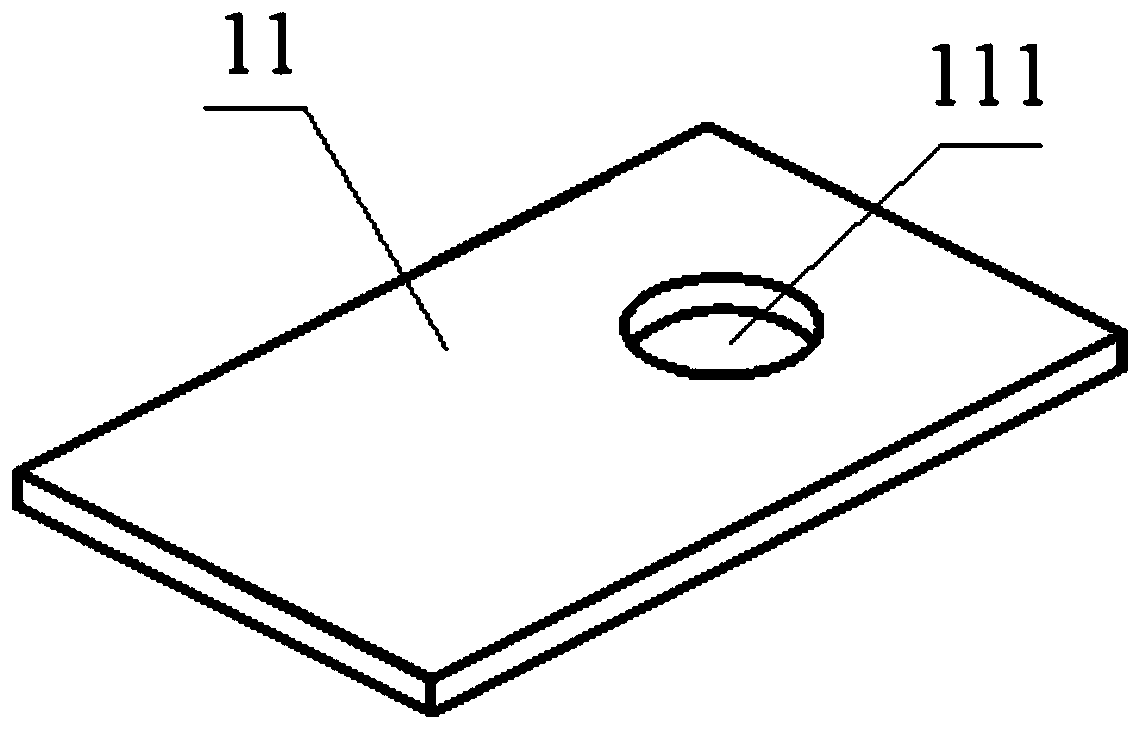
[0036] Such as Figure 3-10 As shown, the present embodiment provides a diaphragm structure 1 , including a diaphragm body 11 on which a cantilever beam valve plate 12 is arranged. Specifically, the diaphragm body 11 is provided with an installation hole 111 , and the cantilever beam valve plate 12 is disposed in the installation hole 111 . Preferably, the diaphragm body 11 can produce a certain elastic deformation, and the installation hole 111 is a round hole.

[0037] The cantilever beam valve plate 12 includes a valve plate body 121 and a cantilever 122 , there are at least two cantilevers 122 , and the valve plate body 121 is arranged in the installation hole 111 through the cantilever 122 . Specifically, the valve body 121 can be circular, square, triangular, polygonal, etc., as long as it can cover the third air hole 31. At least two cantilevers 122 are evenly distributed along the edge of the valve body 121, and one end of the cantilever 122 is connected to the valve ...

Embodiment 2

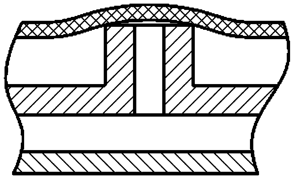
[0048] Such as Figure 11 As shown, the leakage valve in this embodiment is basically the same in structure as the leakage valve in Embodiment 1, the only difference is that the second air hole 22 is not in contact with the diaphragm structure 1 , and there is a gap between them. Through the above setting, in the initial state, the second air hole 22 communicates with the first cavity 4; when inhaling air, a large pressure difference is required to cause the diaphragm body 11 of the diaphragm structure 1 to elastically deform and then close the second air hole 22, but in During the air outlet process, the second air hole 22 is easy to open.

Embodiment 3

[0050] Such as Figure 12 As shown, the leakage valve in this embodiment is basically the same structure as the leakage valve in Embodiment 1, the only difference is that the diaphragm structure 1 is set separately, and the diaphragm structure 1 includes a left diaphragm 13 and a right diaphragm 14, and the left diaphragm 13 is located between the second air hole 22 and the fourth air hole 32, separating the first cavity 4 and the second cavity 5; the right diaphragm 14 is provided with a mounting hole 111, and a cantilever beam valve plate 12 is installed on the mounting hole 111, and the right The diaphragm 14 is located between the first cavity 4 and the third air hole 31 , and the connection between the third air hole 31 and the first cavity 4 is controlled by the cantilever valve plate 12 .


PUM


Abstract

The invention relates to the field of fluid control, in particular to a diaphragm structure and a leak valve. The diaphragm structure comprises a diaphragm body. A mounting hole is formed in the diaphragm body. An overhanging beam valve plate is arranged in the mounting hole and comprises a valve plate body and overhanging beams. The valve plate body is arranged in the mounting hole through the overhanging beams. By adopting the overhanging beam valve plate, the valve plate body is planar, the valve plate body makes planar contact with air vents, different from line contact in the prior art, during working, under the effect of a pressure difference, the valve plate body translates up and down on the whole, the stability is high, the reverse blocking capability is high, the discharge capacity is high, the problems that a leak valve in the prior art is poor in reverse blocking capability and poor in discharge capacity are solved, and no high-pressure cut-off occurs.

Description

technical field [0001] The invention relates to the field of fluid control, in particular to a diaphragm structure and an air leakage valve. Background technique [0002] With the gradual improvement of the fourth-generation electronic sphygmomanometer, the entire air circuit has shrunk to only occupy part of the space of ordinary watches, which puts forward higher requirements for core components such as air pumps and air leakage valves, such as fast response and miniaturization. [0003] The air leakage valve in the prior art utilizes the pressure difference to perform one-way inflation and deflation, and the one-way valve for controlling gas flow mainly has two structures, the integral cantilever beam structure (such as figure 1 ) and umbrella structures (such as figure 2 ). Integral cantilever structure, the elastic body and the valve seat are in line contact, the reverse cut-off is poor, the stiffness of the elastic body is not easy to control, and the flow-through c...

Claims


Application Information

Patent Timeline
Patent Type & Authority Applications(China)
IPC IPC(8): F16K99/00
Inventor 吴垠周京京钟德坤张磊舒培
Owner 常州威图流体科技有限公司
Why Eureka
Try Eureka