A light guide plate and its preparation method

A light guide plate and light guide point technology, which is applied in the field of light guide plates, can solve problems such as uneven thickness distribution of light guide plates, inability to uniform light and light transmission, and poor light transmission performance, and achieve excellent colorless transparency and solve uniformity. The effect of improving light and light transmission and compatibility

Active Publication Date: 2020-05-19
KUNSHAN CHENGTAI ELECTRIC
View PDF8 Cites 0 Cited by
  • Summary
  • Abstract
  • Description
  • Claims
  • Application Information

AI Technical Summary

Problems solved by technology

However, due to the uneven distribution of the thickness of the light guide plate in the traditional light guide plate, the dispersion of the material in the light guide plate is large, the texture is uneven, and the toughness is poor during use, and the damage rate is high. The existing light guide plate cannot It makes the light refract, reflect and scatter well to play the role of soft light, and in the long-term use process, the light transmission performance will deteriorate, which will increase the loss of light energy, and the problem of light uniformity and light transmission cannot be well achieved.

Method used


Image

  • A light guide plate and its preparation method
  • A light guide plate and its preparation method
  • A light guide plate and its preparation method

Examples


Embodiment 1

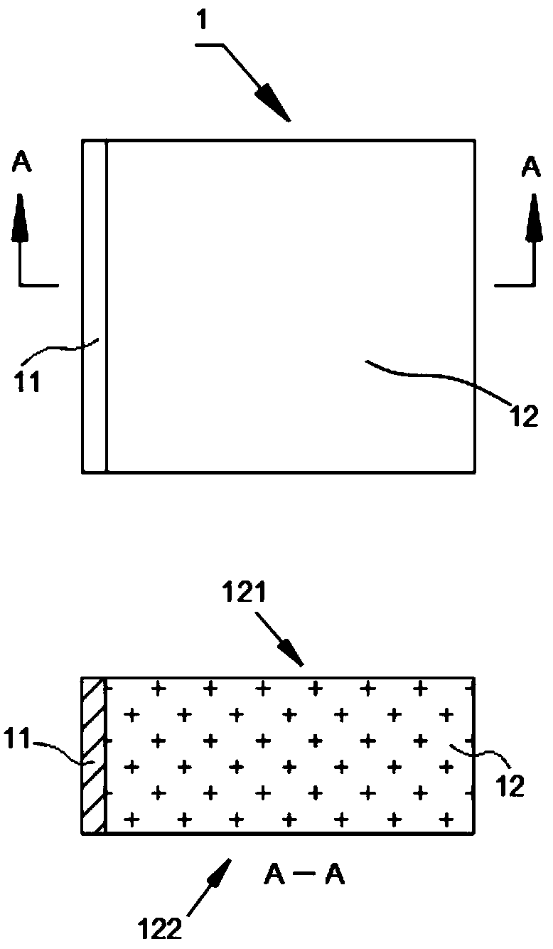
[0043] A light guide plate, the light guide plate 1 includes a light exit surface 122, a back surface 121 and several sides, the light exit surface 122 is set opposite to the back surface 121, the back surface 121 is provided with a light guide point, and the side surfaces are connected to the light exit surface 122 and The back side 121, wherein at least one side is provided with a light entering layer (11), the part 12 of the light guide plate other than the light entering layer 11 is a PS layer, and the light entering layer material is composed of the following components in parts by weight: poly 25 parts of methyl acrylate, 2 parts of microporous hydroxyapatite, 10 parts of n-propyl silicate, 6 parts of cellulose triacetate, 25 parts of acrylonitrile-butadiene-styrene copolymer, 10 parts of ultrafine active silica powder 4 parts, 4 parts of dimethyl silicone oil, 8-11 parts of polymethylpentene resin, 10 parts of polytetrafluoroethylene, 8 parts of octylphenol, 6-13 parts o...

Embodiment 2

[0051] A light guide plate, the light guide plate 1 includes a light exit surface 122, a back surface 121 and several sides, the light exit surface 122 is set opposite to the back surface 121, the back surface 121 is provided with a light guide point, and the side surfaces are connected to the light exit surface 122 and The back side 121, wherein at least one side is provided with a light-introduction layer 11, the part 12 of the light guide plate other than the light-introduction layer 11 is a PS layer, and the material of the light-introduction layer is composed of the following components in parts by weight: polymethyl acrylate 28 parts of ester, 5 parts of microporous hydroxyapatite, 12 parts of n-propyl silicate, 10 parts of cellulose triacetate, 30 parts of acrylonitrile-butadiene-styrene copolymer, 11 parts of ultrafine active silica powder, 4 parts of dimethyl silicone oil, 9 parts of polymethylpentene resin, 11 parts of polytetrafluoroethylene, 12 parts of octylphenol,...

Embodiment 3

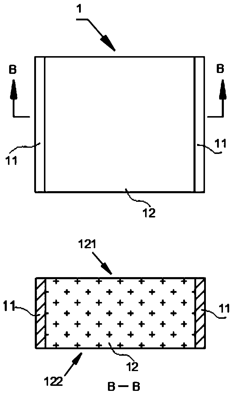
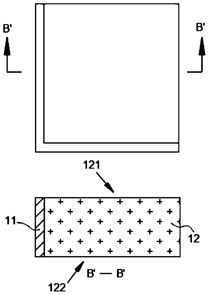
[0059] Using the materials of Example 2, the structure of the prepared light guide plate device is basically the same as that of Example 1, the difference is that the light guide plate 1 is a rectangular plate, and the two sides of the rectangular plate are provided with light-incoming layers 11; the two sides are opposite sides, such as image 3 shown.


PUM

PropertyMeasurementUnit
refractive indexaaaaaaaaaa

Abstract

The invention discloses a light guide plate and a preparation method thereof. The light guide plate comprises a light outgoing surface, a back surface and side surfaces, wherein the light outgoing surface and the back surface are arranged oppositely; the side surface is connected with the light outgoing surface and the back surface; at least one side surface is provided with a light incoming layer; the part outside the light incoming layer of the light guide plate is a PS layer; and the light incoming layer is composed of the following components in parts by weight: polymethyl acrylate, microporous hydroxyapatite, n-propyl silicate, cellulose triacetate, acrylonitrile-butadiene-styrene copolymer, ultrafine activated silica powder, polydimethylsiloxane, polymethylpentene resin, polytetrafluoroethylene, 4-octylphenol, ethylene bisstearamide, ethyene glycol, stearate, acrylic emulsion, polymethylphenyl silicone, thermoplastic polyurethane elastomer, dicalcium phosphate, polyethylene glycol, a stabilizer, and a composite antioxidant. Through mixing the components, the light guide plate is prepared, the stability is strong, the transmittance is good, and light loss can be reduced.

Description

technical field [0001] The invention belongs to the technical field of light guide plates, and in particular relates to a light guide plate and a preparation method thereof. Background technique [0002] The light guide plate uses the optical-grade acrylic plate to absorb the light emitted from the lamp to stay on the surface of the optical-grade acrylic plate. When the light hits each light guide point, the reflected light will spread to all angles, and then destroy the reflection condition and be emitted from the front of the light guide plate. . Through light guide points of various densities and sizes, the light guide plate can be made to emit light evenly. [0003] The light panel design principle originates from the LCD screen of a laptop computer, and is a high-tech product that transforms a line light source into a surface light source. Optical-grade acrylic (PMMA) / PC is used as the base material, and the backlight module technology of LCD display and notebook comp...

Claims


Application Information

Patent Timeline
Patent Type & Authority Patents(China)
IPC IPC(8): G02B6/00C08L33/08C08L55/02C08L1/12C08L27/18C08L23/20C08L33/04C08L83/04C08L75/04C08K13/02C08K3/32C08K3/36C08K5/20C08K5/06C08K5/098
Inventor 盛玉林
Owner KUNSHAN CHENGTAI ELECTRIC
Why Eureka
Try Eureka