Electromagnetic coil for air conditioner
An electromagnetic coil and coil technology, applied in the direction of coils, circuits, electrical components, etc., can solve the problems of electromagnetic coil heating, excessive voltage, coil burning, etc., and achieve the effects of reliable connection, improved safety, and simple and convenient installation.
- Summary
- Abstract
- Description
- Claims
- Application Information
AI Technical Summary
Problems solved by technology
Method used
Image
Examples
Embodiment 1
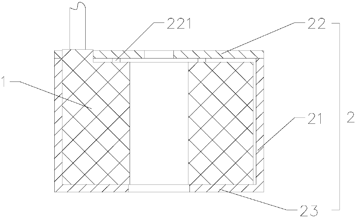
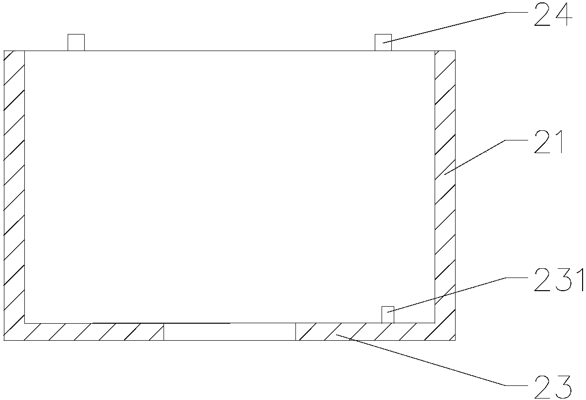
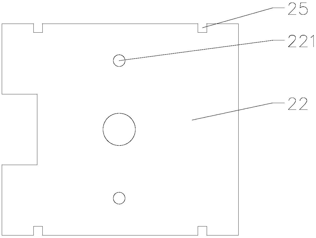
[0036] Such as Figures 1 to 3 As shown, the present invention provides an electromagnetic coil for air conditioning, including a coil body 1 and a magnetically permeable frame 2 with fire-resistant performance. The magnetically permeable frame 2 is sleeved outside the coil body 1. Frame 2 ensures the magnetic conduction function of the coil; the magnetic conduction frame 2 includes a side plate 21 with a “mouth” shape in cross section, an upper cover plate 22 located above the side plate 21 and a lower cover plate 23 located below the side plate 21. The plate 21 forms a closed whole with the upper cover plate 22 and the lower cover plate 23, and surrounds all six sides of the coil body 1, so as to prevent the occurrence of disasters caused by the fire of the coil and improve the safety of the use of the electromagnetic coil; the lower cover plate 23 is provided with There are at least two lower protrusions 231, and the lower protrusions 231 are located on the outer peripheral...
Embodiment 2
[0049] Such as Figures 4 to 6 As shown, the main difference between this embodiment and Embodiment 1 is that the side plate 21 includes an upper side plate 211 and a lower side plate 212, the lower cover plate 23 and the lower side plate 212 are integrally stamped and formed, and the upper side plate 211 and the upper cover plate 22 integrally stamped and formed.
[0050] The side plate 21 includes an upper side plate 211 and a lower side plate 212 , the lower cover plate 23 and the lower side plate 212 are integrally formed by stamping, and the upper side plate 211 and the upper cover plate 22 are integrally formed by stamping. The upper end surface of the lower side plate 212 is provided with a boss 24 , and the lower end surface of the upper side plate 211 is provided with a mounting hole 25 matching with the boss 24 . The advantage of this arrangement is that by dividing the side plate 21 into an upper side plate 211 and a lower side plate 212, the upper side plate 211 a...
Embodiment 3
[0054] Such as Figures 7 to 9 As shown, the main difference between this embodiment and Embodiments 1 and 2 is that the side plate 21 includes a first side plate 213 and a second side plate 214, and both the first side plate 213 and the second side plate 214 are in an “L” shape. , the first side plate 213 is integrally stamped and formed with the upper cover plate 22 , and the second side plate 214 is integrally stamped and formed with the lower cover plate 23 .
[0055] The side plate 21 includes a first side plate 213 and a second side plate 214, the first side plate 213 and the second side plate 214 are both in an "L" shape, the first side plate 213 is integrally stamped with the upper cover plate 22, the second The side plate 214 and the lower cover plate 23 are integrally formed by stamping. The first side plate 213 and the upper cover plate 22 are all provided with a boss 24, and the second side plate 214 and the lower cover plate 23 are all provided with a mounting ho...
PUM
 Abstract
Description
Claims
Application Information
 - R&D
- Intellectual Property
- Life Sciences
- Materials
- Tech Scout
- Unparalleled Data Quality
- Higher Quality Content
- 60% Fewer Hallucinations
Browse by: Latest US Patents, China's latest patents, Technical Efficacy Thesaurus, Application Domain, Technology Topic, Popular Technical Reports.
© 2025 PatSnap. All rights reserved.Legal|Privacy policy|Modern Slavery Act Transparency Statement|Sitemap|About US| Contact US: help@patsnap.com


