
Micro-LED display panel and display device

A technology of micro-light-emitting diodes and display panels, which can be used in radiation control devices, semiconductor devices, electrical components, etc., and can solve problems such as single functions

Active Publication Date: 2021-06-04
HKC CORP LTD
View PDF8 Cites 0 Cited by
  • Summary
  • Abstract
  • Description
  • Claims
  • Application Information

AI Technical Summary

Problems solved by technology

Most of the existing micro-light-emitting diode displays only have a display function and have a single function

Method used


Image

  • Micro-LED display panel and display device
  • Micro-LED display panel and display device

Examples


Embodiment Construction

[0025] The following will clearly and completely describe the technical solutions in the embodiments of the present invention with reference to the accompanying drawings in the embodiments of the present invention. Obviously, the described embodiments are only part of the embodiments of the present invention, not all of them. Based on the embodiments of the present invention, all other embodiments obtained by persons of ordinary skill in the art without creative efforts fall within the protection scope of the present invention.

[0026] It should be noted that if there is a directional indication (such as up, down, left, right, front, back...) in the embodiment of the present invention, the directional indication is only used to explain the position in a certain posture (as shown in the accompanying drawing). If the specific posture changes, the directional indication will also change accordingly.

[0027] In addition, if there are descriptions involving "first", "second" and ...


PUM


Abstract

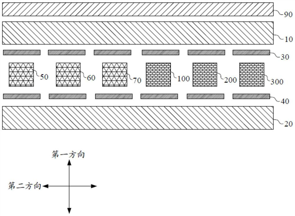
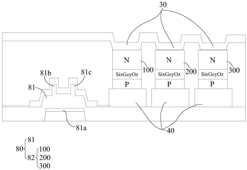
The invention discloses a micro light emitting diode display panel and a display device, wherein the micro light emitting diode display panel comprises: an upper substrate, a lower substrate, an upper electrode, a lower electrode, a first micro light emitting diode, a second micro light emitting diode and a third micro light emitting diode A light emitting diode and an image sensor array, wherein the upper substrate and the lower substrate are arranged at intervals in the first direction; the upper electrode is arranged on the side of the upper substrate close to the lower substrate, and the lower electrode is arranged on the side of the lower substrate close to the upper substrate; The first micro light emitting diode, the second micro light emitting diode, the third micro light emitting diode and the image sensor array are all arranged between the upper electrode and the lower electrode, and the first micro light emitting diode, the second micro light emitting diode, the third micro light emitting diode and the image sensor array are arranged at intervals along the second direction. The micro light-emitting diode display panel provided by the present invention not only has excellent display performance, but also has a scanning function.

Description

technical field [0001] The invention relates to the field of display technology, in particular to a micro light emitting diode display panel and a display device. Background technique [0002] The use of LED (Light Emitting Diode, light emitting diode) in display elements originates from the application of TFT-LCD (thin film transistor-liquid crystal display, thin film transistor-liquid crystal display) backlight module. TFT-LCD is a non-self-illuminating flat-panel display, and its component functions are similar to light control switches, requiring a backlight module to provide a light source. Since TFT-LCD began to flourish in the 1990s, some manufacturers have used LEDs as the backlight of liquid crystal displays, which have the characteristics of high color saturation, power saving, and thinness. However, due to factors such as high cost, poor heat dissipation, and low photoelectric efficiency, it was not widely used in TFT-LCD products. [0003] By the 2000s, white L...

Claims


Application Information

Patent Timeline
Patent Type & Authority Patents(China)
IPC IPC(8): H01L27/15H01L27/146
CPCH01L27/146H01L27/15
Inventor 卓恩宗杨凤云
Owner HKC CORP LTD
Learn More