
Ceramic waveguide filter

A waveguide filter, ceramic filter technology, applied in waveguide devices, electrical components, circuits, etc., can solve problems such as insufficient coupling bandwidth and inability to widen the product passband.

Inactive Publication Date: 2019-05-21
SUZHOU XIE CHENG HARDWARE PROD CO LTD
View PDF3 Cites 4 Cited by
  • Summary
  • Abstract
  • Description
  • Claims
  • Application Information

AI Technical Summary

Problems solved by technology

[0004] With the development of modern communication technology, the miniaturization of communication equipment is an inevitable trend, especially in the 5G era, the miniaturization of communication equipment is particularly important. In 5G communication, filters have also been moving towards miniaturization development, but the reduced size of the filter is contradictory to the communication bandwidth required by reality. After the size is reduced, the coupling bandwidth between frequency and frequency is not enough, resulting in the inability to widen the passband of the product

Method used


Image

  • Ceramic waveguide filter
  • Ceramic waveguide filter
  • Ceramic waveguide filter

Examples


Embodiment

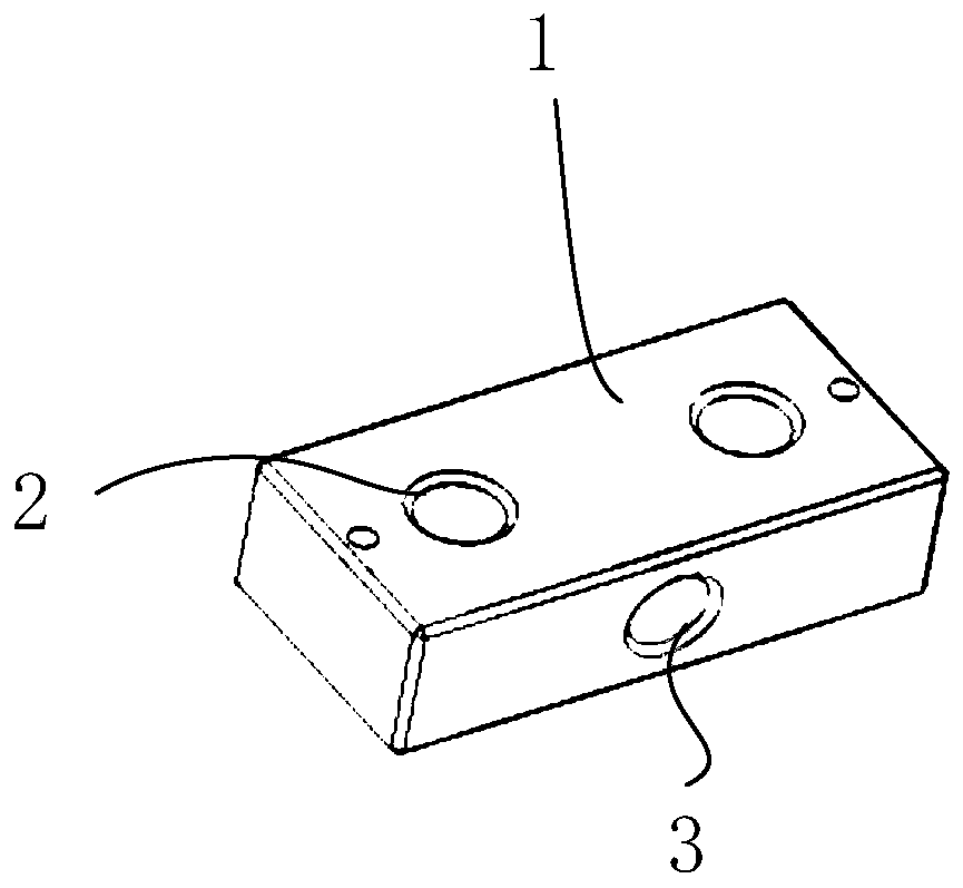
[0025] like figure 1 As shown, a ceramic waveguide filter is provided with a coupling hole 3 groove on the ceramic filter 1 with spaced frequency cavities 2, and the coupling hole groove 3 is opened on the side of the ceramic filter, and is also located between the two frequency cavities 2 Set between, so that the coupling between the two frequency cavities is enhanced, wherein, the formula between the coupling hole slot 3 and the frequency cavity is as follows:

[0026]

[0027] P is the magnetic polarization coefficient;

[0028] M is the coupling coefficient;

[0029] L and D are the length and diameter of the coupling hole, respectively;

[0030] z is half the length of the coupling hole, that is, z=L / 2;

[0031] λ is a constant.

[0032] The coupling holes described in the present invention are cylinders or cuboids, and are generally operated with cylinders, which is convenient for forming and coupling at the same time.

[0033] In the present invention, the coupl...


PUM


Abstract

The invention relates to a ceramic waveguide filter. A coupling hole is formed in a ceramic filter having an interval frequency cavity, and the coupling hole is formed in a side edge of the ceramic filter and is also disposed between two frequency chambers, so that the bandwidth of the filter is widened. The ceramic waveguide filter provided by the invention solves the problem of increasing the coupling bandwidth between the frequency and the frequency after the size of the ceramic waveguide filter is reduced, so that the frequency band of the product is wider.

Description

technical field [0001] The invention belongs to the technical field of ceramic filters, in particular to a ceramic waveguide filter. Background technique [0002] With the continuous development of modern communication technology, the requirements for filters are getting higher and higher. Filter technology with small size, high performance, high power and low cost is particularly important for filters in wireless communication applications. 5G array type Under the application conditions of the antenna, the size of the existing metal cavity filter can no longer meet the requirements of the wireless communication system; for example, the conventional single-channel 20-watt filter, the current size is more than 200X100X30 mm, but the size requirements of the 5G filter Under the size of 50X30X30 mm, otherwise the array antenna solution cannot be realized. [0003] According to the principle of resonant cavity, the resonant frequency in the cavity depends on the size of the cav...

Claims


Application Information

Patent Timeline
IPC IPC(8): H01P1/208H01P11/00
Inventor 周亮田富耕赵嘉炜
Owner SUZHOU XIE CHENG HARDWARE PROD CO LTD
Features
  • Generate Ideas
  • Intellectual Property
  • Life Sciences
  • Materials
  • Tech Scout
  • Unparalleled Data Quality
  • Higher Quality Content
  • 60% Fewer Hallucinations
Learn More