
Antenna, hinge and electronic equipment

An antenna and hinge technology, applied in the field of antenna installation and layout, can solve the problems such as the inability of the antenna to be placed in a hinge with a smaller size, the limited antenna radiation range, and the small size of the hinge.

Active Publication Date: 2021-07-30
HEFEI LCFC INFORMATION TECH
View PDF6 Cites 0 Cited by
  • Summary
  • Abstract
  • Description
  • Claims
  • Application Information

AI Technical Summary

Problems solved by technology

[0002] With the continuous advancement of science and technology, people use more and more electronic devices such as laptops in their study, life and work, and laptops are currently developing in the direction of narrow borders and large screen-to-body ratios. The size of the hinges used in notebook computers is getting smaller and smaller, which makes it impossible to put the antenna into the smaller hinges. At the same time, the existing antenna design also limits the radiation range of the antenna, and there is a radiation dead angle.

Method used


Image

  • Antenna, hinge and electronic equipment
  • Antenna, hinge and electronic equipment
  • Antenna, hinge and electronic equipment

Examples


Embodiment Construction

[0035] In order to enable those skilled in the art to better understand the technical solutions of the present application, the present application will be described in detail below in conjunction with the accompanying drawings and specific embodiments.

[0036] Various aspects and features of the present application are described herein with reference to the accompanying drawings.

[0037] These and other characteristics of the present application will become apparent from the following description of preferred forms of embodiment given as non-limiting examples with reference to the accompanying drawings.

[0038] It should also be understood that, while the application has been described with reference to a few specific examples, those skilled in the art can certainly implement many other equivalents of the application, which have the features of the claims and are thus located. within the limited scope of protection.

[0039] The above and other aspects, features and advan...


PUM


Abstract

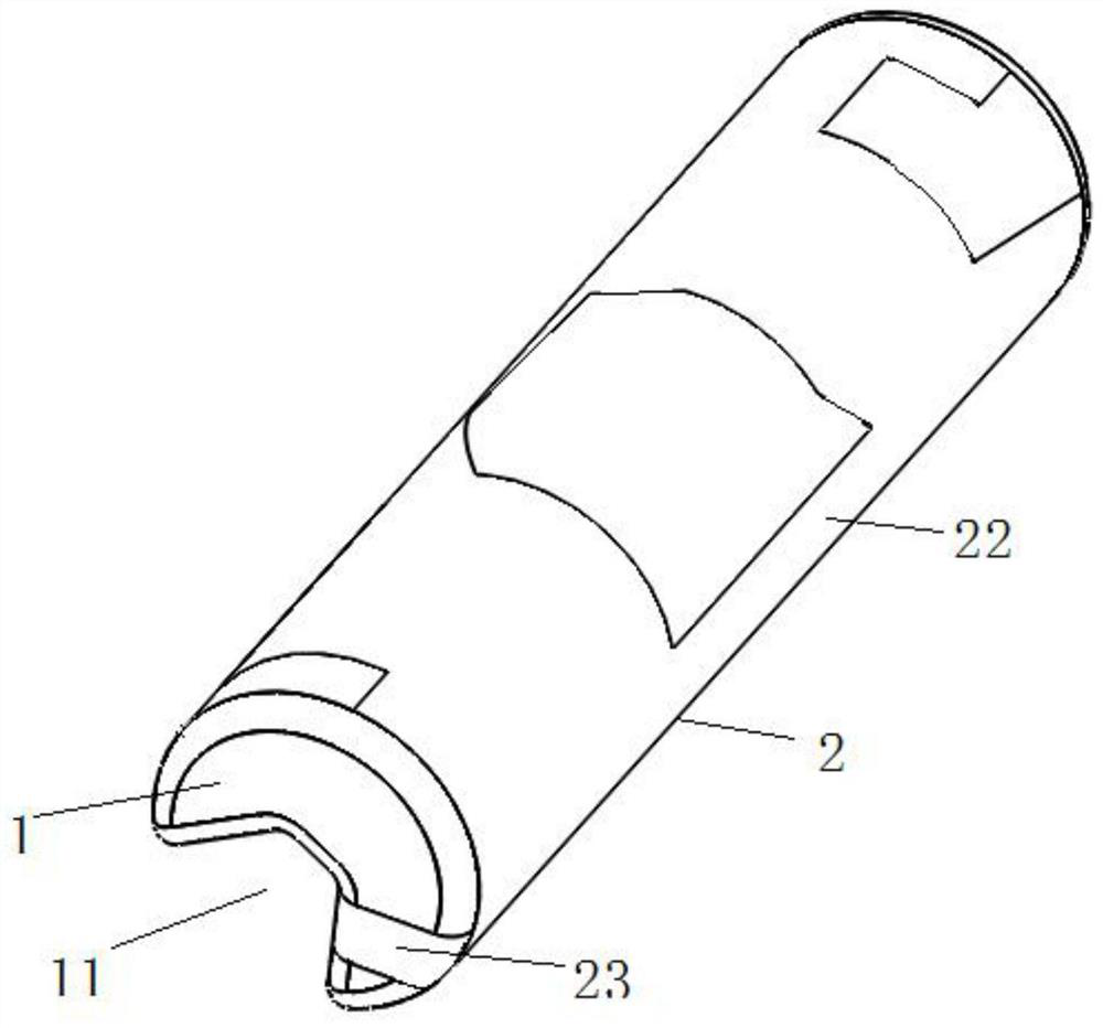
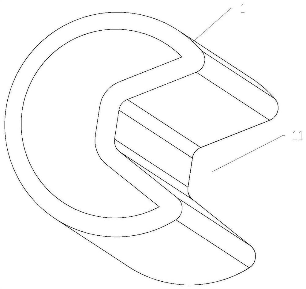
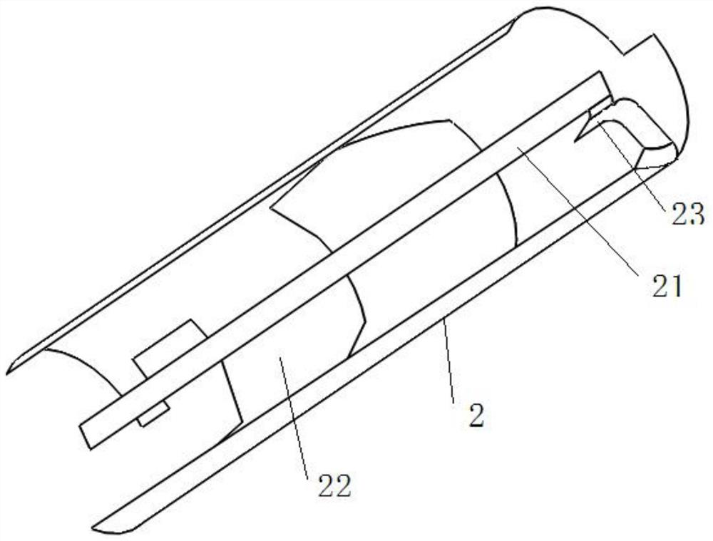
The embodiment of the present application provides an antenna, a hinge and an electronic device. The antenna includes a carrier body and an antenna body. The carrier body is in the shape of a cylinder and has a groove on it. The groove is on a plane perpendicular to the center line of the carrier body. The cross-section on the top is trapezoidal, and the opening of the groove increases along the radial direction of the carrier towards the side away from the centerline; the antenna body includes a first antenna part and a second antenna part, and the first antenna part is arranged on the side of the groove along the centerline direction. The bottom of the groove, the second antenna part is arranged on the outer arc surface of the carrier, the second antenna part can be covered with the entire outer arc surface, and a hollow part is also formed on the second antenna part, and one end of the first antenna part is along the concave The edge of the side wall of the groove is extended to form a first extension for electrically connecting with the second antenna part. The above-mentioned antenna body has good directivity, has a small size, can be installed on a hinge shaft with a small size, and has good performance.

Description

technical field [0001] This application relates to the installation and layout of antennas, especially an antenna, hinge and electronic equipment. Background technique [0002] With the continuous advancement of science and technology, people use more and more electronic devices such as laptops in their study, life and work, and laptops are currently developing in the direction of narrow borders and large screen-to-body ratios. As a result, the size of the hinge used in notebook computers becomes smaller and smaller, making it impossible to put the antenna into the hinge with a smaller size. At the same time, the design of the existing antenna also limits the radiation range of the antenna, and there is a radiation dead angle. Contents of the invention [0003] In view of the above-mentioned problems in the prior art, embodiments of the present application provide an antenna capable of omnidirectional (360-degree) radiation without dead angles, a hinge using the antenna, a...

Claims


Application Information

Patent Timeline
Patent Type & Authority Patents(China)
IPC IPC(8): H01Q1/12H01Q1/36H01Q1/50H01Q1/22G06F1/16
Inventor 姜远远汪建安孟凡乐耿尧郝敬军
Owner HEFEI LCFC INFORMATION TECH
Learn More