
Circuit breaker trolley, switch cabinet and interlocking device of circuit breaker trolley

A technology of interlocking devices and circuit breakers, which is applied in the direction of switchgear, pull-out switchgear, electrical components, etc., can solve the problems of difficult design of interlocking devices, and achieve the solution of difficult design, simple structure, unlocking and Lock-in effect

Active Publication Date: 2019-05-21
PINGGAO GRP +1
View PDF6 Cites 0 Cited by
  • Summary
  • Abstract
  • Description
  • Claims
  • Application Information

AI Technical Summary

Problems solved by technology

[0004] The purpose of the present invention is to provide a circuit breaker trolley to solve the problem in the prior art that the design of the interlock device is difficult due to the lack of mechanical transmission parts of the circuit breaker; the purpose of the present invention is also to provide a switch cabinet; The purpose of the invention is also to provide a kind of interlocking device in this switchgear

Method used


Image

  • Circuit breaker trolley, switch cabinet and interlocking device of circuit breaker trolley
  • Circuit breaker trolley, switch cabinet and interlocking device of circuit breaker trolley
  • Circuit breaker trolley, switch cabinet and interlocking device of circuit breaker trolley

Examples


Embodiment Construction

[0027] Embodiments of the present invention will be further described below in conjunction with the accompanying drawings.

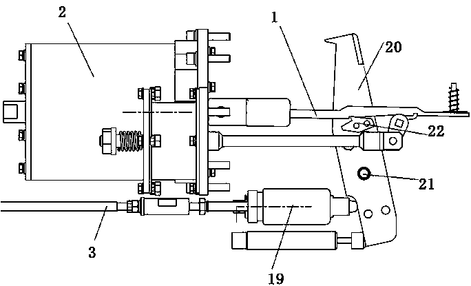
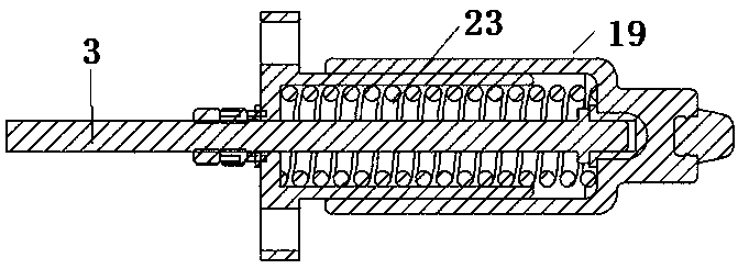
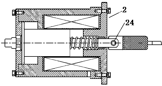
[0028] The specific embodiment of switchgear of the present invention, as Figure 4 to Figure 6As shown, the switch cabinet includes a cabinet body, a circuit breaker trolley and an interlocking device for interlocking the two, wherein the circuit breaker in the circuit breaker trolley is a DC circuit breaker, which includes an arc extinguishing chamber, closing push rod 1, opening Push rod 3, the closing electromagnet 2 that drives the closing push rod 1, and the isolation contact 4 connected to the end of the busbar led by the moving and static contacts of the arc extinguishing chamber. The working principle of the DC circuit breaker is: closing The electromagnet 2 is connected with the closing push rod 1 through the hinge pin 24, and the closing push rod 1 and the block 22 assembled on the movable contact are linked and matched through the fastening s...


PUM


Abstract

The invention relates to a circuit breaker trolley, a switch cabinet and an interlocking device of the circuit breaker trolley. The circuit breaker trolley comprises an arc extinguishing chamber and an opening push rod which is arranged on the outer side of the arc extinguishing chamber and can move in a reciprocating mode; the opening push rod has a first position corresponding to a closing stateof a circuit breaker and a second position corresponding to an opening state of the circuit breaker in a moving process; the circuit breaker trolley is further provided with an interlocking transmission mechanism; the interlocking transmission mechanism comprises a rotating piece which is driven by the opening push rod to rotate in a reciprocating mode; the rotating piece is provided with a pushing part; when the opening push rod is positioned in the second position, the pushing part is positioned in an unlocking position where the pushing part can be matched with the stress end of a lockingmechanism of the interlocking device in a pushing mode to unlock the locking mechanism; and when the opening push rod is in the first position, the pushing part is located above or below the height ofthe unlocking position to avoid the stress end, and then transmission force can be led out from the opening push rod, so that the unlocking and locking of the interlocking device are realized, and the problems of few transmission parts in the circuit breaker and high design difficulty of the interlocking device are solved.

Description

technical field [0001] The invention relates to a circuit breaker trolley, a switch cabinet and an interlocking device thereof. Background technique [0002] In the traction power supply system of urban rail transit, electric energy is transmitted from the static feeder line and catenary of the traction substation to the electric train, and then flows back to the traction substation from the electric train through the rail and the return line. The power supply network consisting of feeder lines, catenary, track loops and return lines is called a traction network. Domestic rail transit subway catenary adopts DC 1500V power supply. The 1500V power supply system consists of positive pole incoming cabinet, negative pole cabinet, feeder cabinet and rail potential limiting device. The feeder cabinet is installed between the positive busbar and the catenary, and is a switch device for direct protection of rail vehicles. The feeder cabinet is equipped with positive busbar, DC fas...

Claims


Application Information

Patent Timeline
Patent Type & Authority Applications(China)
IPC IPC(8): H02B11/133
Inventor 李禹生蒋晓旭张洪铁毕迎华何保营朱苛娄张友鹏韩国辉郭煜敬许兴涛肜连超林麟王向克赵芳帅沙云鹏
Owner PINGGAO GRP
Learn More